Array
Voyager Custom Array is a special version of Voyager born to manage array of telescopes over a single mount. its possible to manage from 2 nodes to 4 nodes. Logic used for managed the array node is the MASTER/SLAVE tecnology where a MASTER organize the job and task of each nodes connected (SLAVE) using communications trough the LAN with a TCP/IP packets. Voyager using internal Application Server to allow communications between MASTER and SLAVE.
All the operations in the array are centralized synchronized parallelized and optimized .. isn't a simple dithering sync but something born just to do array job , result of years of development and real test on the field.
Most important features of Custom Array in Voyager:
- Master - Slave Technology with Application Server Communication System
- Single PC multi instances or separate PCs
- Works in Local, LAN/WAN or mixed Mode
- Guide calibration, Guide execution and Dithering are Syncronized
- Advanced Dithering System managed by Single Node, Multiple Node or Full Nodes
- Centralized and Syncronized AutoFocus with RoboFocus on single star and LocalField on multiple Stars
- Single Mount
- Centralized Dashboard Management on Master
- Centralized Sequence Editor on Master
- Integrable in DragScript
- All the Base License feature are included, also in Slave Version.

Communications between Nodes of Array
The logic behind Array setup is to have 1 MASTER Array Setup and one or more SLAVE Array Setup(s).MASTER and SLAVEs communicate using TCP/IP protocol with the Voyager Application Server included in Voyager. Possible way to implements the array are (all needed Voyager Custom Array license):
- 1 PC for each node with Voyager installed (communications using LAN with a LAN Switch and Ethernet cable or wi-fi connection)
- 1 PC and 1 instance for each node (if controls used in Voyager for setup allow multiple instance and PC have enough resource to manage it)
- mixed mode where you can have 1 PC for node or 1 PC with more instance (example MASTER and 1 SLAVE in one PC in multi instance and 2 PC with Voyager single instance for the other nodes)
In any case Voyager Application must be enabled for each Voyager node and firewall in each PC must be enabled to allow Voyager Application Server communications over TCP/IP ports 5950,5951,5952,5953. Usually when install Voyager and activate Application Server request about opening firewall will be showed automatically, just say OK and allow (needed only 1 time).
For your info Node is every members of the Array.
LAN / WI-FI Settings
If you decide to work in LAN please be sure your PCs are on the same subnet of LAN and have a different IP and are connected togheter if necessary with a LAN switch and ethernet cable in case of physical LAN.
You can check raw LAN communication between PCs using the ping command from windows command line.
If PCs aren't on the same LAN or firewall is not opened you cannot obtain array (or some nodes) to work.
Custom Array Observatory Section
Voyager reserve a new section for the Custom Array, this section called "Custom Array Observatory Section" will be visible in the MASTER of the array and cannot be opened from the SLAVE. You will found an icon dedicated to this section in the main window short menu and main menù:

The Custom Array Section Form in divided in 2 parts, upper the dahsboard dedicated to all the Array elements with data and status and lower the control room with all the command to setup the Array and control it:

Array Dashboard
The Array Dashboard contains one info panel for each array node present in the array included the MASTER, its possible to rearrange position of the panel but not to remove or modify size that is only automatic, the size will be resized with the main windows and the number of panels is locked to the number of array elements allow by license.

The title of the panel report the status of the node connection with a coloured led (green is connected) , the name of the node and if this is a MASTER node or a SLAVE node. Panel cannot be close also if the X command is visible on the windows caption.
All the data in the Panel are referred to the single Node rappresented. Explanation of the fields:
- Connection Status: report the link connection status of the Node related to the Array, connected if the node array is communicating the the MASTER (linked)
- Operative Status: report if the node are running some action or are in IDLE
- Details on Action Running on the Node: report the description of the action running on the node
- P.A of the Rotator: report PA of the Rotator on the node if is present
- Temperature of CCD: report the temperature of CCD on the node if available
- Power Status of CCD Peltier: report the power of CCD peltier on the node if available
- Focuser Position in Step: report the position of the focuser in step of the node
- HFD of last focus done: reporte the last HFD value obtained on autofocus action in the node
- Temperature reported from the Focuser system: report the temperature readed by the focuser system in the node if available
- Time start of the Sequence: report the time when the sequence running was started
- TIme to finish of the Sequence: report (if available) the time when the running sequence will be finished
- TIme elapsed of the Sequence: report the time elapsed by the running sequence
- Target name of th Sequence: report the target name of the running Sequence
- Elapsed % of actual Shot in Sequence: report graphycally and by number the % of elapsed shot
- Table with list of all Shot in Sequence and data: this table show all the list order of the shot will be done or are done or is running, data row represent in order the progressive number, the elapsed % of shot, the filter used,the exposure lenght in s., the bin used, the status of shot, the file name used or that will be used to store the FIT file
- Authentication Status: report if the connection with the related Node is protected under username/password credentials. When is protected a yellow lock icon will be showed.
Control Room
The Control Room allow you to control the Array setting and operation in overall mode or for a single node at time without need to jump to the related Voyager instance.
It is dived in 3 tabs:
- Array: contains configuration of Array, link command and generally all the commands and configurations relative at actions executed by all the nodes in the array at same time
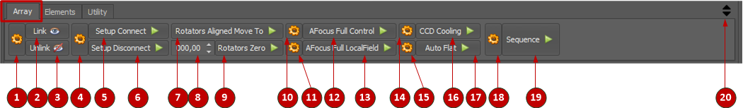
- 1 - Array Setting - Configuring the Array
- 2 - Link - Connect all the node available in the array togheter
- 3 - Unlink - Disconnect all the node available in the array
- 4 - Setup Connect and Disconnect setting - Define setting for execute Setup connection and disconnect
- 5 - Setup Connect - Execute parallelized action to connect setup on all the nodes in the Array (equivalent to startup section connect in a base license)
- 6 - Setup Disconnect - Execute parallelized action to disconnect setup on all the nodes in the Array (equivalent to startup section disconnect in a base license)
- 7 - Rotators Aligned Move To - Execute parallelized action to align rotators on all the nodes in the Array at requested PA (movement will be done according set in Array settings)
- 8 - PA Value - Value of PA to use for Rotators
- 9 - Rotators Zero - Execute parallelized action to align rotators on all the nodes in the Array at PA of 0° (movement will be done according set in Array settings)
- 10 - AFocus Full Control Settings - Settings of the AFocus Full Control Action
- 11 - AFocus Full LocalField Settings - Settings of the AFocus Full LocalField Action
- 12 - AFocus Full Control - Execute Parallelized action to AutoFocus all the nodes in the Array using RoboStar (Single star autofocus)
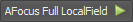
- 13 - AFocus Full LocalField - Execute Parallelized action to AutoFocus all the nodes in the Array using Localfield (All stars on the field)
- 14 - CCD Cooling Settings - Settings of the CCD Cooling Action
- 15 - AutoFlat Settings - Settings of the AutoFlat Action
- 16 - CCD Cooling - Execute Parallelized action for Cooling operations in all the CCD in the Array
- 17 - AutoFlat - Execute Parallelized action to take Flat for all the nodes in the Array (so many limitation are included in this action please refer to dedicate paragraph)
- 18 - Sequence Settings - Setting of the Sequence Action
- 19 - Sequence - Execute Parallelized Sequence Action in all the nodes of the Array (Master run sequence, Slave execute sequence command from Master)
- 20 - Double black arrow - Close or Open in toggle the Control Room Window
- Elements: contains commands and settings for operate directly on a single node at time
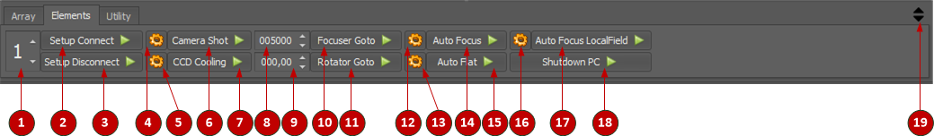
- 1 - Array Node Index - select the index node where to apply to settings and action in the this tab
- 2 - Setup Connect - connect the setup in the selected array node
- 3 - Setup Disconnect - disconnect the setup in the selected array node
- 4 - Camera Shot Settings - settings of the Camera Shot action
- 5 - CCD Cooling Settings - settings of the CCD Cooling action
- 6 - Camera Shot - running a shot action in the selected array node
- 7 - CCD Cooling - cooling operations on the CCD in the selected array node
- 8 - Focuser Position for Focuser Goto - position of focuser in step to use for Focuser Goto
- 9 - PA for Rotator Goto - PA position in degree to use for Rotator Goto
- 10 - Focuser Goto - move the focuser to the selected position in the selected array node
- 11 - Rotator Goto - move the rotato to the selected PA in the selected array node
- 12 - AutoFocus Settings - settings of the Aufocus action
- 13 - AutoFlat Settings - settings of the AutoFlat action
- 14 - AutoFocus - execute autofocus action in the selected array node (RoboStar single star)
- 15 - AutoFlat - execute autoflat action in the selected array node
- 16 - AutoFocus LocalField Settings - settings of the autofocus localfield
- 17 - AutoFocus LocalField - execute autofocus action in the selected array node (LocalField all stars)
- 18 - ShutDown PC - execute a shutdown of the PC in the selected array node (you will lost connection to this array node)
- 19 - Double black arrow - Close or Open in toggle the Control Room Window
- Utility: contains commands dedicate to configuration array setting retrieving or special operations on a single node at time
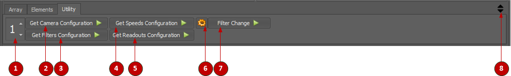
- 1 - Array Node Index - select the index node where to apply to settings and action in the this tab
- 2 - Get Camera Configuration - retrieve the information about Camera (If is Color Camera or not, CMOS Gain and Offset capabilities)
- 3 - Get Filter Configuration - retrieve the filters configuration in the selected array node, this data are necessary and will be store in the array settings
- 4 - Get Speed Configuration - retrieve the speed of CCD control in the selected array node, this data are necessary and will be store in the array settings
- 5 - Get Readout Configuration - retrieve the readut of CCD control in the selected array node, this data are necessary and will be store in the array settings
- 6 - Filter Change Settings - setting for filter change action
- 7 - Filter Change - change the filter in the selected array node
- 8 - Double black arrow - Close or Open in toggle the Control Room Window


Setup Custom Array - Step by step List
To configure an Array this is the operations to do in order, take your time:
- install Voyager in each PC will be run the array
- copy and paste the serial number of each node obtained after installation and send to support to receive the right license
- install the license to transform the Voyager installations to Voyager Custom Array version
- configuring each node one at time like if you running a normal Voyager with all setup (mount, pate solving, autofocus....etc), goal is to align the camera rotation (or if you have a motorized rotators obtaing a PA reading for do the zero offset of rotators) and to get filters offset to use in the array autofocus (autofocus in Voyager array will be done with a default filters and a focuser steps offset will be applied during sequence shot according filters difference)
- For each node
- (goal is to align camera rotation) plate solve you actual position and get camera PA. If you doesn't have rotator just choose a PA reference get it and use in all nodes, if you have rotator you will use the PA readed to obtain and set a zero offset in the array setup
- usign autofocus calculate filters offset
- select one of the filter like reference and put 0 in the offset value
- do a series of autofocus with the choosed filter in previous point and obtaing an average of focus steps
- do a series of autofocus with each other filters , obtain an average of focus step, subtract to the reference filter, this value must be inserted in the offset field of the filter
- example A : you have choosed L filter like reference filter in Master, after 5 autofocus you found the average steps is 12930, doing autofocus for 5 times with R filter you have found average is 12945, subtracting 12945- 12930 you have 15 steps .. this is the offset to put in the offset field
- example B : you have choosed L filter like reference filter in Master, after 5 autofocus you found the average steps is 12930, doing autofocus for 5 times with G filter you have found average is 12920, subtracting 12920 - 12930 you have -10 steps .. this is the offset to put in the offset field
- configuring setup that wil be used (in the node) in each single array Node (MASTER and SLAVEs)
- Activate Voyager Application Server in each node and alow firewall rule to be added to the OS
- prepare list of IP of array node and ports for the next steps
- running voyager in the SLAVEs without connecting setup
- configuring the array setting in the MASTER
- test the connection in Array setting form
- Link the array from the control room
- Connect all setup of array nodes from the control room
- retrieve for each node (MASTER and SLAVE) the setting data using the utility in the control room:
- Get Camera Configuration (each node)
- Get Filters Configurations (each node)
- Get Speeds (each node)
- Get Readout Modes (each node)
- running some operations for the array if work correctly (shot, filter change, autofocus)
- setting the filter offset for all array nodes if you need, remember that the Custom Array always do autofocus on Sequence usign Default Filter and working with offset
- congratulations your array are ready to work
Setup Custom Array - Single Array Node Setup
To configure an Array, you must first configure the individual array elements.
See the Setup section for information on setting up a single node (which will be a component of the array).
After you have align the camera PA (or offset rotators PA) and have get the filters offset you must create a profile for the final array setup configuration (see notes about in step by step list)
In MASTER setup all kind of controls you have and need.
In SLAVE only this kind of controls are configurable (if you need):
- Camera
- Mount (Only "Array Virtual Mount")
- Rotator
- Flat Device
In SLAVE absolutely not Configure controls for:
- Guiding
- Planetarium
- Plate Solving
- Blind Solving
- Dome
- Weather
- Observing Conditions
- SQM
- SafetyMonitor
- Viking
Activate the Application Server in Voyager SetupForm

When your individual array elements are setup, in all the SLAVE arrays you have to set the mount choice to "Array Virtual Mount".
Note: All the mount options and configurations will disappear, the MASTER Array will fully control the Mount.

Setup Custom Array - Array Setup
Next step is to configure the Array:
Click the Section menu and choose the Custom Array Observatory icon:
The Custom Array Observatory main window will be opened.
In the Control Room select the Array tab and click on the array setup icon .

the configuration windows of Array will be opened at center screen:

- Array Elements box contains settings for communications and link of the array nodes, according your license only the node allowed will be editable
- first element to configure is always the MASTER, you can have only one MASTER in your array so you will found a radio option Master already selected.
- check the flag Use for each node will compose the array , if this flag is unchecked the array will not be considered in any operations can be useful if you want to temporarly remove a node of the array cause failure or manteinance or simple you dont want to use in some kind of job
- edit the Name of each Node, using a text short that can help you to easily recognize the setup also on the log
- fill the Host / IP and Port fields, edit the Name of PC or IP address that hosting the Voyager instance for the selected node. MASTER doesn't need IP or host because the PC is the same PC where the configuration and all operations will be managed. You can retrieve IP and port of the PC using the OS utilities or starting Voyager in the node and opening the Application Server monitor, at beginning of the log text you will fund the list of IP address and port (do not use localhost). Generally fort he port each first instance of voyager have port 5950 assigned, 5951 for the 2nd instance, 5952 for the 3rd instance and 5953 for the 4th instance
- press Reset if you want to bring back the value to the default
- press Default Port if you want to fille the Port field with default port used by Application Server in Voygaer (5950)
- press Test if you want to try connection to the host/ip and port you have setup for the Node, a message about test result will be reported at screen
- Default Setting tab contains field necessary for generic and sequence actions
- Rotator P.A. Zero contains data to manage the zero PA value of all the rotators in the array (if you use it). In an Array to obtain the same PA not necessary to single PA in node will be the same. With this offset you will be able to pointing all the rotator with a correct angle value to have finally all the same PA. Do this operations to fill the data the first time you configure the Array:
- set MASTER rotator to zero PA
- solve an image and get the PA from monitor log
- if you are able to offset the zero in your driver use it otherwise put the PA solved like zero value in MASTER PA field
- for each node put the rotator to zero PA and solve image, get the PA solved, offset by MASTER PA field and put the difference in the NODE PA field
- Focus Filter contains the default fitler used for focus in each array nodes. Voyager Array use at now final offset to adjust focus from default filter to the final asked during the sequence or autofocus command in the Control Room
- Is Color Sensor is a flag retrived automaticall during the Get Camera Configuration explained in the Step by step list to configure Array, If set mean the camera is a color camera
- Can Set CMOS Gain is a flag retrived automaticall during the Get Camera Configuration explained in the Step by step list to configure Array, If set mean the camera is a CMOS camera and Voyager can set the gain
- Can Set CMOS Offset is a flag retrived automaticall during the Get Camera Configuration explained in the Step by step list to configure Array, If set mean the camera is a CMOS camera and Voyager can set the offset
- Autofocus Not Available this is a manual flag if setup in the node not allow use of Autofocus or if you want to exclude the node from autofocus tasks
- Cooling Not Available this is manual flag that remove the options for the node to activate and manage the cooling or if the camera in the node doesn't have peltier capability
- Rotator P.A. Zero contains data to manage the zero PA value of all the rotators in the array (if you use it). In an Array to obtain the same PA not necessary to single PA in node will be the same. With this offset you will be able to pointing all the rotator with a correct angle value to have finally all the same PA. Do this operations to fill the data the first time you configure the Array:
- Array Filters Config tab contains field necessary for configure Filter list in each node and the focus offset by filter always for each node
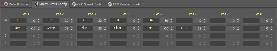
- Important Note! Max 8 filters can be managed by Voyager Custom Array
- Filter Label cannot be edited, value must be retrieved directly from the Control Room using tab Utility , selecting the node and press command Get Filter Configuration. This operation mus be done when you have finished to configure all the remain settings of the Array. Please refer to Array Single Node Utility Operations instructions
- Offset Numeric Spin contains number of step (negative or positive) to apply to the filter to leave the focus correct. Must be inserted after the filter list will be populated like for the previous point. To obtain filter offset do this operations FOR EACH NODE including MASTER the first time you configure the Array:
- select one of the filter like reference and put 0 in the offset value
- do a series of autofocus with the choosed filter in previous point and obtaing an average of focus steps
- do a series of autofocus with each other filters , obtain an average of focus step, subtract to the reference filter, this value must be inserted in the offset field of the filter
- example A : you have choosed L filter like reference filter in Master, after 5 autofocus you found the average steps is 12930, doing autofocus for 5 times with R filter you have found average is 12945, subtracting 12945- 12930 you have 15 steps .. this is the offset to put in the offset field
- example B : you have choosed L filter like reference filter in Master, after 5 autofocus you found the average steps is 12930, doing autofocus for 5 times with G filter you have found average is 12920, subtracting 12920 - 12930 you have -10 steps .. this is the offset to put in the offset field
- CCD Speed Config tab contains the various speed usable (if present and supported) in the CCD management shot for each node
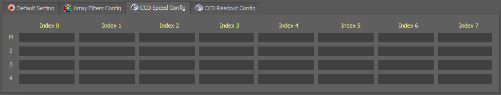
- Important Note! Max 8 speed index can be managed by Voyager Custom Array
- Index Label cannot be edited, value must be retrieved directly from the Control Room using tab Utility , selecting the node and press command Get Speed Configuration. This operation mus be done when you have finished to configure all the remain settings of the Array. Please refer to Array Single Node Utility Operations instructions
- CCD Readout Config tab contains the various Readout Mode usable (if present and supported) in the CCD management shot for each node
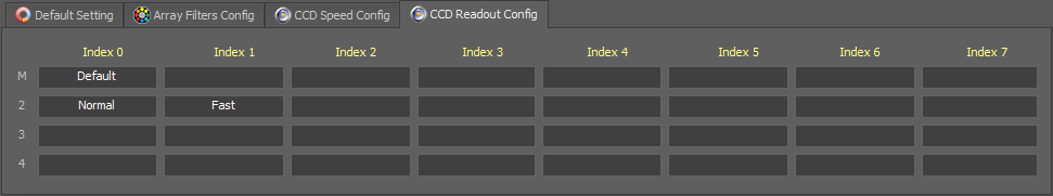
- Important Note! Max 8 Readout Mode index can be managed by Voyager Custom Array
- Index Label cannot be edited, value must be retrieved directly from the Control Room using tab Utility , selecting the node and press command Get Readout Configuration. This operation mus be done when you have finished to configure all the remain settings of the Array. Please refer to Array Single Node Utility Operations instructions
- Authentication tab contains the credentials for authentication on each nodes if needed, this depends on how is configured the application server in each node
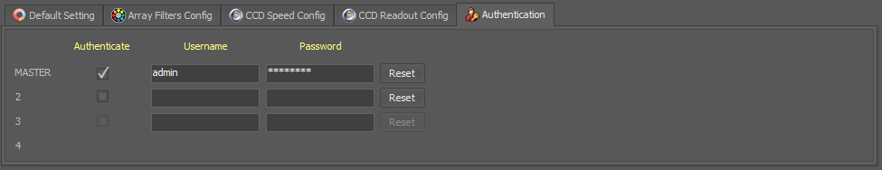
- Authenticate: check it if the node need authentication (equal the application server in the node have the authentication method set up to username/password)
- Username: username to use for authentication, is case sensitive
- Password: password to use for authentication, is case sensitive
- Reset: to reset data to empty fields
- Various Panel contains the setting dedicated the general aspect of Array
- Array Virtual Mount Data Send Interval: time interval in seconds between each mount data send from MASTER to each SLAVE
- Array General Data Send Interval: time interval in seconds between each detailed data send from each SLAVE to MASTER
- Remote Setup Connection Timeout: timeout in seconds before abort setup connection action
- "Connect All Setup" Strong Connection Result: check this flag if you want that the connection setup action report OK (not ERROR) only if all the nodes in the array are able to connect all setup, useful if control trough dragscript the connect and want be sure all the node are usable
- Focus Retry in Autofocus Action: number of autofocus retry in case of failure during autofocus all array actions
- Interval Time Between Action AutoRetry: interval time in seconds between an action repeat due to a failure
- Communication Protofo File Log(*): customize the log level info inside the array communications log file (nothing = no messages logged, No Polling = messages polling between node will be not reported, All = all the messages will be logged). If you use All file log can be really big, check the filesystem space regularly


Array Link and Connection
To establish the link between all your array setups just press the Link button ![]() available into the Array control box.
available into the Array control box.
NOTE: This operation will not connect your setup, but only link the Voyager instances.
The screen is an example of Link between a MASTER and one SLAVE over the same PC using a second istance of Voyager (image onf 2 monitor):

To make fully functional the array you must connect all setup using dedicated action in the Array Operations
Array Operations
Array operations work on all nodes of the array, can be operte only from the MASTER using the commands in the Array tab of the Control Room
For Array Setup (first icon on the left of the Array Operations) please referer to dedicated instructions here.
- Link -
 - Connect all the nodes available in the array togheter. Result of the Connection will be reported in the Array Dashboard in the Connection Status Field. Link mean connection of the MASTER to the Application Server of the SLAVE. Communications will be established and array are ready to accept all the commands. Link to the array doesn't mean to start the setup in each node, for this exists a dedicate command. Possible value result is CONNECTED - CONNECTION ERROR , during Connection a CONNECTING status will be reported
 - Unlink -
 - Disconnect all the node available in the array. Result of the Connection will be reported in the Array Dashboard in the Connection Status Field. Unlink mean disconnection of the MASTER to the Application Server of the SLAVE. Communication will be close and array element are not reachable from the MASTER. Operations within SLAVE will be not allowed and an error will be throw. Unlink doesn't mean a disconnection of the setup in the SLAVE that will continue to have the same previous status
 - Setup Connect -
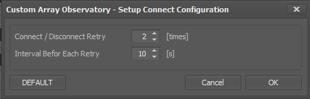
- The setup of all nodes will be connected at same time (parallelized) with more retry in case of failure before report error for the node
- Connect / Disconnect Retry - retry in case of failure in connect remote setup before report general error to the user
- Interval Before Each Retry - interval in seconds before retry setup connect in one node that have failed
- DEFAULT - restore default setting in the configuration fields
- Setup Disconnect -
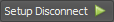
- The setup of all nodes will be disconnected at same time (parallelized) with more retry in case of failure before report error for the node
- Connect / Disconnect Retry - retry in case of failure in disconnect remote setup before report general error to the user
- Interval Before Each Retry - interval in seconds before retry setup disconnect in one node that have failed
- DEFAULT - restore default setting in the configuration fields
- Rotators Aligned Move To -
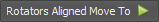 - Execute parallelized action to align rotators on all the nodes in the Array at requested PA (movement will be done according offset in Array settings)
- Rotators Zero -
 - Execute parallelized action to align rotators on all the nodes in the Array at PA of 0° (movement will be done according offset in Array settings)
 - AFocus Full Control -
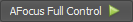
- Execute Parallelized action to AutoFocus all the nodes in the Array using RoboStar (Single star autofocus). Solving and pointing will be done only in the MASTER
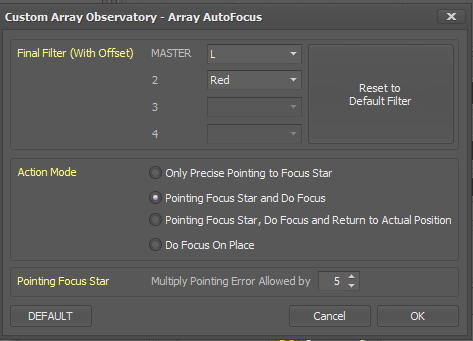
- Final Filter (With Offset) : focus in Custom Array are always done with default filter selected in the Array Setup , after focus finished the filter we be changed to the one asked in this setting and offset set in Array Setup will be apply according difference between default filter and final filter. Its possible to choose different filter for different node
- Reset to Default Filter : all the node will use the default filter configured in Array Setup
- Action Mode: define exactly the various step will be done during the Autofocus Action
- Only Precise Pointing to Focus Star: just pointing a right star for autofocus and exit
- Pointing Focus Star and Do Focus: pointing a right star for autofocus and do autofocus and exit
- Pointing Focus Star, Do Focus and Return to Actual Position: pointing a right star for autofocus, do autofocus , go back in a precise way to previous position and exit
- Do Focus On Place: try to do autofocus on the actual place without pointing any stars, you must be lucky to found a right star for focus, probably the action will fail
- Point Focus Star Multiply Pointing Error Allowed by: define the amount of error (multiply by times the original in the MASTER setting) to precise pointing the focus star (use a high value to fstening the operation). Focus on all start will start when the pointing procedure on MASTER will be terminated
- DEFAULT - restore default setting in the configuration fields
- AFocus Full LocalField -
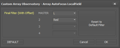
- Execute Parallelized action to AutoFocus all the nodes in the Array using Localfield (All stars on the field). Mount will not be moved and the focus will be done in the actual position
- Final Filter (With Offset) : focus in Custom Array are always done with default filter selected in the Array Setup , after focus finished the filter we be changed to the one asked in this setting and offset set in Array Setup will be apply according difference between default filter and final filter. Its possible to choose different filter for different node
- Reset to Default Filter : all the node will use the default filter configured in Array Setup
- DEFAULT - restore default setting in the configuration fields
- CCD Cooling -

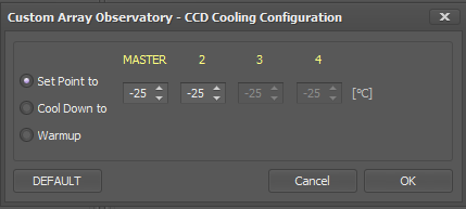
- Execute Parallelized action for Cooling operations in all the CCD in the Array
- Set Point to : using internal firmware of each CCD in each node to reach pelterier requested temperature in °C
- Cool Down to : using Voyager ramp cooling down of each CCD in each node to reach pelteer requested temperature in °C
- Warmup : reach ambient temperature of each CCD in each node with a ramp
- DEFAULT - restore default setting in the configuration fields
- AutoFlat -

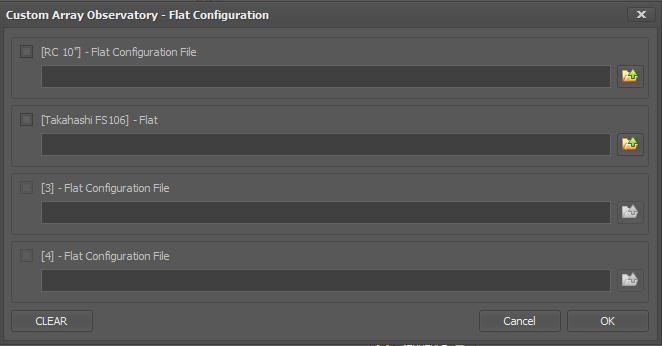
- Execute Parallelized action to take Flat for all the nodes in the Array (so many limitation are included in this action please refer to dedicate paragraph)
- Flat Configuration File for node MASTER - select configuration file for autoflat action to run in MASTER node
- Flat Configuration File for node 2 - select configuration file for autoflat action to run in node 2
- Flat Configuration File for node 3 - select configuration file for autoflat action to run in node 3
- Flat Configuration File for node 4 - select configuration file for autoflat action to run in node 4
- CLEAR - remove all configuration file from setting
- Important Note! Some kind of autoflat actually are not supported, flat on the sky can be done only on the master. Flat with the panel can be done only with fixed panel and command management in MASTER array.
- Sequence -
 - Execute Parallelized Sequence Action in all the nodes of the Array (Master run sequence, Slave execute sequence command from Master). Please refer to Array Sequences instructions.


Array Single Node Operations
Array Single Node Utility Operations
Array Sequences
Array DragScript Integration
FAQ
- Can i focus the slave nodes of the array without have Array connected ?
- Answer is yes, but due to fact that the mount is connected only to the master you must cloning the Voyager profile on the slave an changing mount control from Array Virtual Mount to a real mount (you must switch mount connection to the slave PC in case of using another PC and not secondary instance of Voyager) or ASCOM simulator. In this case you can use LocalField to for autofocus beacuse for RoboStar you must enable also the Plate Solving control. Generally you are working in a complex environment best way is to use Array facilities from the Master.
- Answer is yes, but due to fact that the mount is connected only to the master you must cloning the Voyager profile on the slave an changing mount control from Array Virtual Mount to a real mount (you must switch mount connection to the slave PC in case of using another PC and not secondary instance of Voyager) or ASCOM simulator. In this case you can use LocalField to for autofocus beacuse for RoboStar you must enable also the Plate Solving control. Generally you are working in a complex environment best way is to use Array facilities from the Master.