OnTheFly
OnTheFly Workspace
The OnTheFly workspace is the main Voyager workspace for performing actions in real time, as opposed to from a DragScript, Voyager's scripting language.

In OnTheFly, you can do many things, including:
- Find coordinates for a target object by name
- Plate solve or blind solve an existing FITS image
- Enter desired RA and DEC coordinates
- Slew your telescope to these coordinates (goto)
- Sync the mount with coordinates
- Create and run an imaging session for a target, with one or more filters and exposures and many configurable options
- Create and run a session to automatically take flat exposures
- Run an external EXE or script
- Slew the scope to a specified RA and DEC, take an exposure, plate solve the result, and re-slew until the plate solved position is within a specified error tolerance ("precision pointing")
- Perform an autofocus operation
The OnTheFly workspace contains both simple and compound actions. Simple actions, such as slewing the mount to a target, make use of one piece of equipment or software. Simple actions are used when you are operating your equipment manually, one operation at a time.
Compound actions automate more complex functions such as taking a series of images with a sequence. When executing a compound action, Voyager orchestrates the operation of multiple pieces of equipment and software, taking appropriate actions based on responses from individual components. E.g., if a weather sensor is attached, Voyager may suspend a sequence on bad weather and resume when weather improves.
Status of executing actions is shown in the Monitor Window. See that section of the Wiki for important information, such as message color coding, regarding messages that appear in the Monitor Window.

Entering the OnTheFly Workspace
You can enter the OnTheFly workspace two different ways:

- Click the OnTheFly icon in the command bar at the top of the window

2. Click the Section menu and then click the OnTheFly icon in the ribbon menu
OnTheFly Workspace Screen
When you enter the OnTheFly workspace, you will see a display similar to this:
The OnTheFly workspace is divided into the following areas:
- Target Coordinates J2000
- Solved Coordinates J2000
- Solving Referenced FIT
- Session
- Utilities
- Actions
We will go over each of these areas in the follow sections.
Target Coordinates J2000
The Target Coordinates J2000 area lets you search for a target by name and slew to it:

- Name: Type the name of an object whose coordinates you want to find. All possible notations are accepted including those of your connected planetarium software or online catalog (which online catalog is used? I don't think any are configured in Setup?)
- Fast Find: Click the Fast Find button to search for the object in the "Name" field. If found, its J2000 coordinates will populate the RA and DEC boxes. Fast FInd use the control planetarium configured in Voyager setup
- SESAME: Click this button to perform a lookup of the object in the "Name" field in the SESAM name resolver database. If found, the object's coordinates appear in a pop-up box. Click OK to enter those coordinates in the RA and DEC fields
- RA and DEC: Right Ascension and Declination of the object in the "Name" field. The RA and DEC fields can be filled out manually, or by the Fast Find,
 Object Finder, or SIMBAD lookup
 - Transit: force to redraw transit graph if the target name and RA and DEC field was fullfilled
- Goto: Slew the mount to the listed RA and DEC coordinates. This is a simple goto, not precision pointing (where a plate solve and re-slew if needed occurs)
 : click left button to copy the RA and DEC coordinates to clipboard, click the right button to paste the RA and DEC coordinates on the clipboard in the Target coordinates
- : Click this button to bring up the Voyager Object Finder, in this example, it is already populated with the results of a search for M42:

- Find: Type the name of an object to lookup in the field at the top and click the Find button to search for information on the object
- Use: Use this results of the search as the current target (puts the coordinates in the Target Coordinates J2000 RA and DEC fields) and close the window
- Clear: Clear the results of the search
- Get Selection: Populate the RA J2000 and DEC J2000 field with the coordinates of the selected object in planetarium (if one is selected)
- Get Center: Populates the RA J2000 and DEC J2000 fields with the coordinates of the center of the field where the telescope is currently pointing
- The graph to the right of the Name, RA J2000 and DEC J2000 fields has the same information as the Target widget in the Status window. See that documentation for a detailed discussion. In short, the graph shows the altitude of the target object over the hours of darkness, with the red and green lines representing the target's rise and set time, the blue line representing transit time, and the gold line representing the current time
- If the search succeeds, the data table contains extensive information about the target object. Note that you may have to use the scroll bar on the right to see all the information Not all information is available for every object:
- Object Name: Primary object ID / name
- Name 2: Secondary object ID / name
- Object Type: Type of object: list of object type depends on the planetarium control you have choose, refer to his manual
- RA (Topocentric): Object's Right Ascension based on observer's location
- Dec (Topocentric): Object's Declination based on observer's location
- RA (2000.0): Object's J2000 Right Ascension
- Dec (2000.0): Object's J2000 Declination
- Azimuth: Object's azimuth position at the time of the search
- Altitude: Object's altitude at the time of the search
- Major Axis: Size of the object's major axis in minutes, if available
- Minor Axis: Size of the object's minor axis in minutes, if available
- Magnitude: Object's magnitude (brightness)
- Rise Time: Local time that the object rises above the local horizon
- Transit Time: Local time that the object crossed the meridian
- Set Time: Local time that the object sets below the local horizon
- Hour Angle: Object's distance from the meridian - negative is before the meridian, positive is after
- Air Mass: Relative amount of the atmosphere that light from the object is passing through to the observer's location. 1.0 is directly overhead. 2.0 means the object has to pass through twice as much atmosphere to reach the observer. The less atmosphere between the observer and the object, the better the image
- Sun Distance (au): Object's distance from our Sun in AU - astronomical units
- Name 3...X: Additional catalog designations for the object
- Spectral: Objects spectral data if available
- Flamsteed-Bayer: Catalog ID if available
- Source Catalog: Source for the information in this table
- Date: Observer's local date
- Time: Observer's local time
- Constellation: Constellation in which the object appears
- Constellation (Abgrev.): Abbreviation of the constellation in which the object appears
- Magnitude B: Object's magnitude with a B filter
- Magnitude V: Object's magnitude with a V filter
- Screen X: coordinates X in pixel in planetarium windows
- Screen Y: coordinates Y in pixel in planetarium windows
- Parallax: Object's parallax (change in position at opposite ends of the Earth's orbit around the sun)
- Proper Motion RA: Object's motion against the background stars in RA
- Proper Motion Dec: Object's motion against the background stars in Dec
- Position Error RA: Calculated object position error in RA
- Position Error Dec: Calculated object position error in Dec
- Sidereal Time: Current sidereal time
- Julian Date: Current Julian Date
- Click Distance: if is a click selection the object retrivied the distance from the clik point and the closest recognized object in planetarium
- Light Years: Object's distance in light years
- Parsecs: Object's distance in parsecs
- Catalog Number: Object's catalog number
- Constellation Number: Constellation number of object's constellation
- Click the red X in the top right corner to close the window without using the search results as the new target coordinates
Solved Coordinates J2000
The Solved Coordinates J2000 panel of the OnTheFly workspace contains coordinates of the most recent plate solved image and some action buttons that can be taken with respect to those coordinates:

- RA, DEC, PA and Res: The coordinates (RA and Dec), position angle (PA), and resolution (image scale in arc-seconds/pixel) of the last image that was manually plate solved
- GoTo: Click this button to slew the mount to the RA and Dec positions given here. This is a simple command to slew the mount, not precision pointing with a plate solve and error correction or rotator move
- SYNC: Issue a Sync command to the mount with the RA and Dec coordinates from these fields. This is a useful way to synchronize your mount at the start of the night. Slew the mount so it has a clear view of the sky, take an image, plate solve it, and then Sync the mount with this command. Now subsequent GoTo operations should be close to the intended target, assuming your mount's polar alignment is good
 : this button move to orange backcolor the RA and DEC field and allow to insert manually a coord for the Sync
- : click left button to copy the RA and DEC coordinates to clipboard, click the right button to paste the RA and DEC coordinates on the clipboard in the Solved coordinates
- Store West Pier Side: Click this button to inform Voyager that the mount is on the west side of the pier, pointing east of the meridian. This is only done once at the first use of the mount's profile so Voyager can understand the actual pier side relative to the information returned by the mount's driver when using the ASCOM pier side report (see Mount Setup). If your mount setup tells Voyager to infer pier side from the current scope position, this is not needed.
Blind Solve and Sync
It is useful to perform a blind solve and sync ("or blind sync") operation at the beginning of a session, especially if you have just set things up and your mount is not yet performing accurate slews (Go To's).
You can do this from OnTheFly and also from a DragScript.
From OnTheFly:
- Slew to a part of the sky where you can take an image with enough stars to do a plate solve
- If your mount's reported position is accurate enough to do a normal Plate Solve, click the "Plate Solve Actual COORD" button
- If the normal Plate Solve fails, or if your mount's reported position is not accurate enough to do a normal Plate Solve, click the "BLIND Solve" button
- Once you have a successful plate solve, click the SYNC button


Solving Referenced FIT
This panel of the OnTheFly workspace is for plate solving and blind solving a FITS file. This can be useful if you want to slew the mount to the same position that was used to take an image in the past where you have the FITS file. Plate solve or blind solve the FITS file with this panel, store the solved coordinates in the Solved Coordinates J2000 panel, and then issue a GOTO or Precise Pointing command from the OnTheFly workspace to line the scope up perfectly with the previously taken image.
By "Referenced FIT" we mean FITS files with header values of XPIXSZ, YPIXSZ, FOCALLEN, OBJCTRA, or OBJCTDEC. The values indicate X and Y size of the pixels in microns, the optical system's focal length, and the presumed coordinates of the center of the image.

- Folder icon: Click the folder icon and browse to find a FITS file that you want to plate solve or blind solve with either a local solver or nova.astrometry.net
- Plate Solve FIT: Plate solve the FITS file using the locally configured plate solver such as PinPoint, TheSkyX ImageLink, All Sky Plate Solver, or PlateSolve2
- Blind Solve FIT: Blind solve the FITS file using the locally configured blind solver such as All Sky Plate Solver or TheSkyX ImageLink All Sky
- Astrometry.Net Web Solve: Blind solve the FITS file using the nova.astrometry.net website. This requires an Internet connection
Session
Voyager can run an automated imaging session, in which one or more exposures are taken using one or more filters of a single target image, along with a complete set of instructions to manage Cooling, Pointing, Tracking, Plate Solving, Meridian Flip, Guiding including Dithering, Autofocus, and error management. Voyager can also run multiple sequences inside a DragScript, which offers complete startup to shutdown control of a full night's imaging of multiple targets.
Voyager can also run automated sessions to obtain the flat images used in image calibration. A flat session can include multiple filters and an arbitrary number of exposures through each filter. During a flat session, Voyager can manage a flat fielding device, and automatically determine the necessary exposure length to achieve the desired image brightness (ADU).
Running a Sequence
The Session panel of the OnTheFly workspace contains controls to define and run sequences for imaging targets and creating flats.

- : Click the top gear icon to bring up the Sequence Configuration dialog. See the Sequence Configuration page for more information on creating a sequence

- Sequence: Click the Sequence button with the single green triangle to start the sequence. If the Confirm for OnTheFly Sequence box is checked in Voyager Setup, a pop-up window will ask for confirmation before starting the sequence
 : Click the double-blue triangle icon to start the sequence with additional startup options:

- Normal Start: Just start the sequence, same as if you clicked the Sequence button with the green triangle
- Just Precise Pointing and Start Shot: Perform a precision pointing action (slew, plate solve, re-slew if needed to correct errors) and then start taking exposures. This is useful if you know that you don't have to do some of the time consuming actions associated with running the sequence with all options, such as doing an autofocus operation.
- Manual Override: Gives you fine control over specific actions to perform or not when running the sequence:
- Initial Precise Pointing Target: If checked, before doing anything else, perform precision pointing to the target coordinates
- Initial Focus: If checked, perform an initial autofocus before starting the sequence
- Initial Guide Calibration: If checked, instruct the guiding software to perform a calibration run before starting the sequence
- Precise Pointing Before First Shot: If checked, perform a precision pointing action before taking the first exposure. Done to correct any significant pointing errors introduced by Guide Calibration or AutoFocus Goto
Taking Automatic Flats
- : Click the bottom gear icon to bring up the Auto Flat configuration dialog:

See the Auto Flat page of the Wiki for detailed information the Auto Flat configuration dialog
Auto Flat: Click the Auto Flat button with the green triangle to run the Auto Flat session
Utilities
The Utilities panel of the OnTheFly workspace contains several miscellaneous operations:

- Sync on Park Position: Works only if Simulate Parking is selected in Park / Unpark panel of the the Mount Setup dialog. Attempts to Sync the mount to the coordinates supplied in the "Simulate Parking" setup, so be sure the mount is in this position before clicking this button. Just do a Sync, to use with a mount driver that lost its position when powered up, for example the FS2 system
- : Click the gear icon to the left of the Good Night button to bring up the Good Night configuration dialog where you can define actions to take place on clicking the Good Night button. This is intended to be the last thing you do when shutting down for the night.

- Run this Program/Script BEFORE: Click the button with "..." to bring up the Run External Program / Script dialog - see below for information about this dialog. Defines an arbitrary program or script to run at the start of the Good NIght operation
- Select this Filter on Camera: If checked, move the filter wheel to the specified filter
- Async Warmup: If checked, send a command to the camera to warm up the sensor and immediately continue with the next step of the Good Night operation (do not wait for the warm up to finish)
- Sync Warmup: If checked, send a command to the camera to warm up the sensor and wait until the warm up finishes before continuing with the next step of the Good Night operation
- Park: Park the mount
- Run this Program/Script AFTER: Click the button with "..." to bring up the Run External Program / Script dialog - see below for information about this dialog. Defines an arbitrary program or script to run at the end of the Good NIght operation

- Program/Script: Click the "..." button to select the program or script to run
- Arguments: Command line arguments to be passed to the program or script when invoking it
- Wait For Program/Script: If checked, wait for the program or script to return before continuing (synchronous execution)
- Wait / Timeout: If Wait for Program/Script is checked, this is the number of milliseconds to wait until timing out
- On Timeout Kill Program/Script: If checked, and the "Wait for Program/Script" option is checked, and the "Wait / Timeout" time period has elapsed, terminate the external program or script
- Continuing with the Utilities Panel:
- Goto Near Zenith: Slew the mount to a position pointing near the zenith (directly overhead)
- Run External Script/EXE: Run an arbitrary external program or script
- Goto AltAz: Slew the mount to the position configured by clicking the gear icon to the left of the Goto AltAz button
- : Click the gear icon to the left of the Goto AltAz button to configure the action taken when pressing the Goto AltAz button
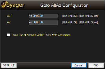
- ALT: Altitude in DD:MM:SS.sss to slew the mount to when clicking the Goto AltAz button
- AZ: Azimuth in DD:MM:SS.sss to slew the mount to when clicking the Goto AltAz button
- Force Use of Normal RA/DEC Slew with Conversion: If checked, convert the specified ALT and AZ coordinates to equivalent RA and DEC coordinates and issue a Goto RA / DEC command to the mount. Use this if your mount does not accept a Goto ALT / AZ command
- Default: Restore the Default settings for this dialog
- Cancel: Exit this dialog without making changes
- OK: Save changes and exit this dialog

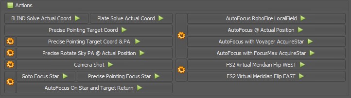
Actions
The Actions panel of the OnTheFly workspace contains immediate actions you take to perform plate solving, autofocus, single image exposures and FS2 Virtual Meridian flip operations:

Plate Solve Actions

- BLIND Solve: Click this button to take an exposure with the selected plate solve settings at the current scope location and submit it to your selected blind solving method
- Plate Solve Actual Coord: Click this button to take an exposure with the selected plate solve settings at the current scope location and submit it to your selected plate solving method
- Precise Pointing Target Coord: Click this button to perform a precision pointing operation to the coordinates given in the Target Coordinates J2000 panel of this workspace. No rotator task with this action. The precision pointing operation commands the mount to:
- Slew to the target coordinates
- Take an exposure using the selected plate solve settings
- Plate solve the image. If the plate fails, try to blind solve the image if the "Use Blind Solving If Plate Failed on Precise Pointing" option is checked in Plate Solve Setup, Plate Solving Watchdog
- Determine the offset between the target coordinates and the plate solved coordinates and compare it to the Precision Pointing Max Allowed Error in Mount setup
- If the error is greater than the max allowed error, issue a slew command to the mount to move it to correct the error
- Repeat steps 2 through 5 until the error is less than the max allowed error
- Precise Pointing Target Coord & PA: Click this button to perform a precision pointing operation to the coordinates given in the Target Coordinates J2000 panel of this workspace and precision rotating of rotator to the PA given in setting form of the action.
- : Click this icon to bring up the Configuration dialog
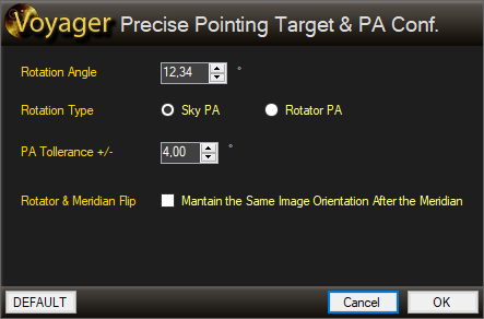
- Rotation Angle: an arbitrary angle that can be a Rotator PA or Sky PA, depends on following setting.
- Rotation Type: define if the rotation angle is the rotator angle (rotator PA) reported from the driver (and with offset if asked to Voyager in Sync) or the Sky angle (Sky PA) chosen with web dashboard VirtualFOV or planetarium or another system. If you select Sky PA Voyager will use the Plate solve PA result to rotate the rotator to the right angle. If you select the Rotator PA Voyager will just rotating rotator using drive angle at desidered value, no correction using the plate solved PA will be done
- PA Tollerance +/-: if the PA of rotator is inside the interval given the position will be declared ok and rotator will not be rotate.
- Rotator & Meridian Flip: "Mantain the Same Image Orientation After the Meridian" if checked force Voyager to shot the target with same orientation in the images taken before anf after meridian. In this case if you have chosen Rotator PA like Rotation type the rotator will be flipped if the mount is after the meridian, if you chosen Sky PA the PA will retained also after the meridian triggering a rotator flip.Use this flag is useful also to use always the same guide star in case of use of OAG or system with high focal lenght.
- Default: for default settings
- Cancel: to exit from then form without changing not
- OK: to store the parameters
- The precision pointing operation commands the mount to:
- Slew to the target coordinates
- Rotate to the Rotation angle if you choose Rotator PA or wait for the first solved image to check the Sky PA and the virtual offset to apply (this operation also will check for your meridian side to understand if is necessary to flip rotator)
- Take an exposure using the selected plate solve settings
- Plate solve the image. If the plate fails, try to blind solve the image if the "Use Blind Solving If Plate Failed on Precise Pointing" option is checked in Plate Solve Setup, Plate Solving Watchdog
- Determine the offset between the target coordinates and the plate solved coordinates and compare it to the Precision Pointing Max Allowed Error in Mount setup
- Determine if its necessary to rotate again the rotator to get the right PA in case of Sky PA mode requested
- If the error is greater than the max allowed error, issue a slew command to the mount to move it to correct the error
- Repeat steps 2 through 5 until the error is less than the max allowed error and PA of rotator in tollerance

Camera Actions

- Camera Shot: Take an exposure at the current scope position using the settings selected by clicking the adjacent gear icon
- : Click this icon to bring up the Test Shot Configuration dialog

- Filter: Select the filter to use for the test shot
- Exposure: Enter the exposure time in seconds for the test shot
- Binning: Select the binning to use for the test shot
- SubFrame: Select the size of the image to use for the test shot from the drop down list

If you are using the ASI Camera native driver (not ASCOM) which allows setting Gain and Offset, the following two settings appear:
- Gain: Set the ASI Camera gain value to the number in the spinner control. Click the magnifying glass icon to select Gain from a preset
- Offset: Set the ASI Camera offset value to the number in the spinner control. Click the magnifying glass icon to select Offset from a preset
- DEFAULT: Change settings to the default values (Default is first filter in wheel, 10s , binning 1 and full frame)
- Cancel: Close the window without saving changes
- OK: Save changes and close the window
Focus Star Actions
Voyager can automatically choose a focus star, or you can specify one manually. The Focus Star actions are where you manually choose the focus star. The AutoFocus actions, described beow, are where Voyager automatically chooses a focus star.

- : Brings up the OnTheFly Focus Star Configuration dialog:

- : Click the icon to bring up the Object Finder dialog and type in the name or catalog ID of your desired focus star
- Left and Right RA and DEC Coordinates: The RA and DEC focus star coordinates on the left are used before the meridian. The focus star coordinates on the right are used after the meridian.
- <-Swap->: You can store the coordinates of two different focus stars. Click the <-Swap-> button to swap the coordinates. The Goto Focus Star, Precise Pointing Focus Star, and AutoFocus on Star and Target Return buttons use these coordinates.
- Goto Focus Star: Click this button to slew to the focus star coordinates. If the mount is pointing before the meridian, the focus star coordinates on the left will be used. If the mount is pointing after the meridian, the focus star coordinates on the right will be used
- Precise Pointing Focus Star: Click this button to perform a precision pointing operation to the focus star coordinates. Precision pointing will slew to the star, take an exposure, plate solve, and re-slew until the actual position is within the error tolerance specified in setup. Before meridian star coords will be used if mount is actually before meridian or viceversa after meridian star coords.
- AutoFocus On Star and Target Return: Click this button to perform a precision pointing operation to the focus star's coordinates, perform an autofocus operation, and then return to the target coordinates as designated in the Target Coordinates J2000 panel in this workspace. Before meridian star coords will be used if mount is actually before meridian or viceversa after meridian star coords.
AutoFocus Actions
There are two videos for AutoFocus:
AutoFocus Setup and First Light Wizard
AutoFocus
The AutoFocus actions can perform LocalField (multiple star) and VCurve (single star) autofocus operations. The VCurve operations can be performed at the current scope position, or with either Voyager or FocusMax AcquireStar, which selects a suitable focus star based on your autofocus setup settings.

- : Brings up the AutoFocus Configuration dialog from which you can select the filter to use in these AutoFocus Actions.

- Filter: Choose the filter to use with AutoFocus from the dropdown list
- DEFAULT: Sets the filter to the default setting , default filter setting is the first filter in the wheel
- Cancel: Close the window without saving changes
- OK: Save the settings and close the window
- AutoFocus RoboFire LocalField: Click this button to perform a LocalField (multiple star) autofocus operation at the current scope position
- AutoFocus @ Actual Position: Perform a VCurve (single star) autofocus operation using a suitable star at the current scope position
- AutoFocus with Voyager AcquireStar: Use Voyager's AcquireStar routine to move to a suitable focus star based on your autofocus setup settings. Perform a VCurve (single star) autofocus operation on that star and then return to the current target.
- AutoFocus with FocusMax AcquireStar: Use FocusMax's AcquireStar routine to move to a suitable focus star. You must configure FocusMax's AcquireStar routine in FocusMax before executing this command. Then perform an autofocus operation. A FocusMax autofocus only will be performed .. non an Robostar or other autofocus type will allowed to use
FS2 Virtual Meridian Flip Actions

- : Brings up the FS2 Virtual Meridian Flip window:

- Azimuth for WEST FLIP (DD MM SS): degrees to use for enter in WEST flip
- Azimuth for EAST FLIP (DD MM SS): degrees to use for enter in EAST flip
- Altitude (DD MM SS): degress to use for simulating meridian flip
- Move North For: to simulate meridian flip
- Move South For: to simulate meridian flip
- Do Final Blind Solving and Sync: When the Virtual Meridian flip finishes, perform a blind solve and sync operation to ensure Voyager knows where the mount is actually pointing
- Default: Fills out the fields in this window with the default settings, default value is on the image above
- Cancel: Close the window without saving any settings
- OK: Save settings and close the window
- FS2 Virtual Meridian Flip WEST: Perform an FS2 Virtual Meridian Filp operation (mount starts or finishes on the WEST side)
- FS2 Virtual Meridian Flip EAST:Perform an FS2 Virtual Meridian Filp operation (mount starts or finishes on the EAST side)