Difference between revisions of "Quick Start"
Voyager>Rowland m |
m (1 revision imported) |
(No difference)
| |
Latest revision as of 18:28, 11 October 2020
Quick Start Video
There is a video covering the material in this tutorial on the Voyager Astro Imaging YouTube channel:
Quick Start
In this tutorial we will walk through the steps to:
- Setup a minimal Voyager Profile (configure your equipment) using ASCOM simulators
- Select a target to image
- Define a sequence to take a series of exposures
- Run the sequence to take the exposures
We will use the ASCOM simulators so everyone can do this tutorial. You can substitute your actual equipment, but you will find it helpful to create a simulator profile that matches your real equipment, so we recommend doing that first.
Many Voyager actions depend on having a connected profile. With a simulator profile that matches your gear, you can create and test sequences and scripts without connecting to your actual equipment.
After completing this exercise with the simulator profile, you can create a profile based on your real equipment and the image-taking sequence you create here should work with your real gear.
Prerequisites
You should have the following software installed before starting this tutorial:
- Voyager: Follow the Installation instructions. You can do this tutorial with the Demo, Trial or Basic versions of Voyager.
- ASCOM: ASCOM Platform 6.x https://ascom-standards.org
- The ASCOM platform comes with the simulators needed for this Quick Start exercise
Configure a Simulator Profile
Voyager uses profiles to store a description of your equipment and various settings that you use while imaging. You can create as many profiles as you like.
Profile definitions are stored on disk, in a location of your choosing or by default in the Voyager\Profile directory - see the Installation page for more details on folders, and the Profile section to read more about profiles.
Profiles can contain information many things, but for this Quick Start, we will create a minimal configuration containing a Camera and a Mount.
Let's get started! Run Voyager if it is not already running.
- Click the Section menu item and then the Setup icon:
Camera Setup
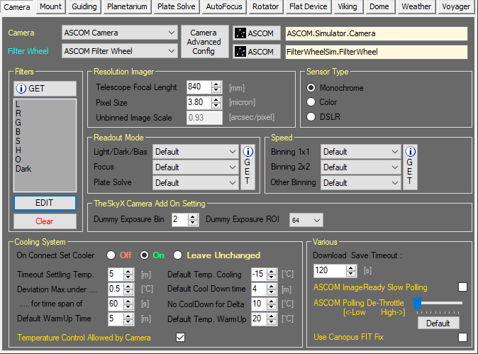
- Click the Camera button to bring up the Camera setup form. Here is what the dialog will look like when we are finished:
- Click the drop-down list next to the Camera label. Choose ASCOM Camera from the list.
- Click the top button of the two ASCOM buttons
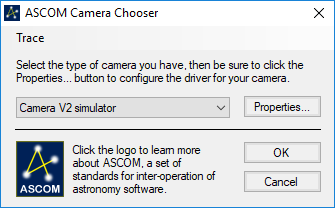
 to bring up the ASCOM Camera Chooser window:
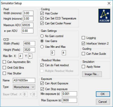
- Select Camera V2 simulator from the drop-down list and then click the Properties button to bring up the Simulator Setup window. Fill out the fields as shown to simulate a ZWO ASI1600MM Cool camera:
- Click OK to save your Camera Simulator settings
- Click OK on the ASCOM Camera Chooser to save your camera choice
Filter Wheel Setup
- Next we will set up an ASCOM Filter Wheel simulator
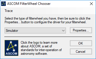
- Choose Simulator from the drop-down list
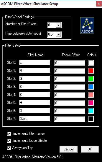
- Click the Properties button to bring up the Filter Wheel Simulator configuration dialog and enter settings to match these:
- Click OK to save your Filter Wheel Simulator setup and close the window
- Click OK on the ASCOM Filter Wheel Chooser to save your choice and close the window
Now we need to populate the Filters section of the Camera setup dialog.
- Try clicking the Get button. For some filter wheels (or camera software such as Maxim DL or TheSkyX), your filter selections will automatically populate the Filters panel of the Camera setup workspace. As of this writing, the ASCOM Filter Wheel Simulator does not support this command
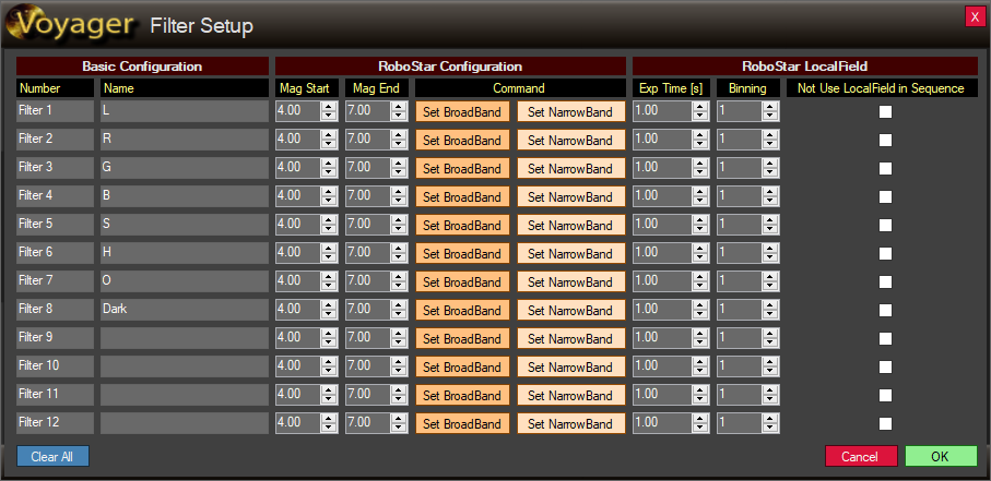
- If your filter names were not automatically read, enter them manually in the Filter Setup dialog.
- Click the EDIT button in the Filters panel
- Enter the filter names in the Basic Configuration column labeled Name and click OK:
- For more information on this dialog, read the Filter Setup section of Camera Setup
Other Camera Setup
- Enter the focal length and pixel size of the simulated telescope in the Resolution Imager panel
- Here we used the values for an Esprit 120 refractor (840 mm focal length) and ASI1600MM Cool camera (3.8 micron pixels). This is one of the fields that should match your actual gear when you create a simulator profile to use when building sequences and scripts without connecting to your gear
- For Sensor Type, choose Monochrome
- Under Cooling System, choose these values:
- The Readout Mode, Speed, TheSkyX Camera add On Setting and Various panels don't matter for this tutorial
Congratulations, you have finished setting up your camera!
Now let's setup a simulated mount.
Mount Setup
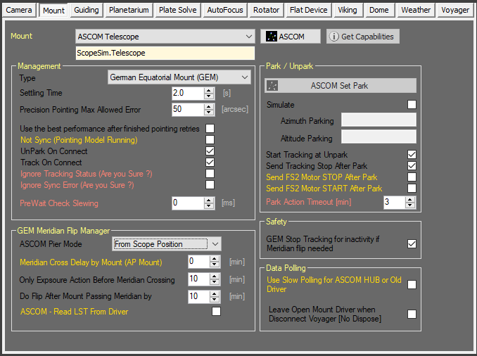
- While in the Setup workspace, click the Mount button to open the Mount setup window. It will look like this when we are done:
- Select ASCOM Telescope from the drop-down list next to the Mount label
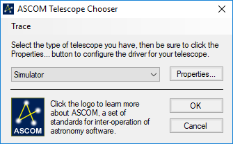
- Click the ASCOM button to bring up the ASCOM Telescope Chooser
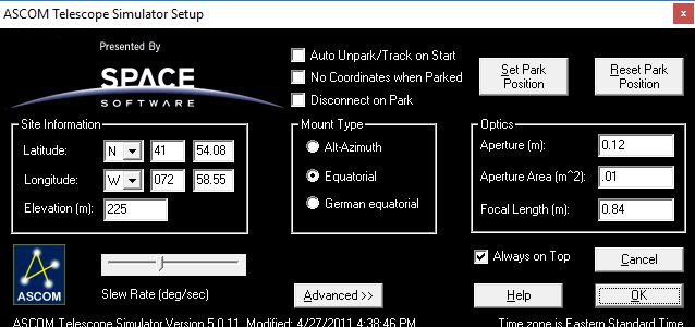
- Select Simulator from the drop-down list and click the Properties button to bring up the ASCOM Telescope Simulator Setup:
- Fill out the values as shown. You can use your own Latitude, Longitude and Elevation, but if you do, you may get different results later in this tutorial
- Click OK to save your settings
- Click OK in the ASCOM Telescope Chooser to save your mount (telescope) choice
- In the Management panel, change the Settling Time to 2 seconds to speed up the simulated gotos
- Check the other settings against the Mount setup window above - we used defaults for everything else, so you shouldn't have to change any other values
Congratulations, you have setup your simulated mount!
You can certainly experiment with setting up more simulated gear in this profile, but nothing else is required for this tutorial.
Save the Profile
By default, the settings you just entered will be saved in a profile on disk with the filename Default.v2y.
Let's save our profile under a new name so we can load it later and modify it to match our own equipment.
- Click the Profile menu:
- Click Save As
- Enter Quickstart Tutorial as the file name
- Click OK to save the profile to disk
Now let's connect to our profile so we can choose a target and create an imaging sequence.
Connect to the Simulator Profile
Since we just finished defining a profile, we don't have to load it - it is already the active profile.
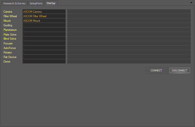
- Click the Section menu item and then the Startup icon:
- Our profile, with three things defined, is shown in this window
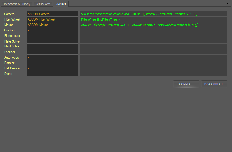
- Click the CONNECT button and Voyager connects to our profile:
That's it! We are now connected to our profile.
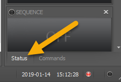
Look on the right of the Voyager main window. Make sure the Status window is selected - click the Status tab at the bottom of the right column:
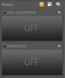
Before you connected, it was a stack of gray boxes that looked like this:
After connecting to your profile, Status widgets display information about the connected devices:
Read more about the Status window in this section.
Now let's select a target to image!
Select a Target to Image
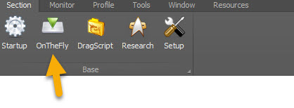
Click the Section menu item and then OnTheFly to enter Voyager's OnTheFly workspace:
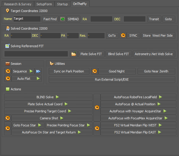
The workspace looks like this:
Since we will be instructing the mount to slew to our target, it is important that Voyager knows exactly where the mount is pointing.
If your mount is on a permanent pier, or if you know that the coordinates it reports are accurate, it is not absolutely necessary to do a SYNC operation before slewing to your target.
However, in many cases it is helpful to do a "blind solve and sync" or simply "blind sync" operation at the start of the night to be sure your mount knows where it is pointing.
Since we are using simulators in this Quick Start, plate solving is not functional so the following two steps won't work.
- If you are using your real equipment and you are under the stars, you can do a blind sync by clicking the Plate Solve Actual Coord button in the Actions panel, and then the SYNC button in the Solved Coordinates J2000 panel.
- If the plate solve fails, usually because your mount's actual position is too far from its reported position, click the BLIND Solve button in the Actions panel and then the SYNC button in the Solved Coordinates J2000 panel.
Now let's continue our Quick Start by picking a target to shoot!
- Pick a target that is in the sky tonight. As this is written, M42 is up, so I'll type M42 in the field next to Name in the Target Coordinates J2000 box:
- If you have an Internet connection, click the SIMBAD button and Voyager will lookup M42 using the SIMBAD online service.
- Click OK in the popup window showing the results of the SIMBAD search, and Voyager will populate the RA and DEC fields with M42's coordinates
If you don't have an Internet connection, just type the RA and DEC coordinates shown in this screenshot into the RA and DEC fields.
If we had configured a Planetarium in our Profile, such as the excellent and free Cartes du Ciel https://sourceforge.net/projects/skychart/ , or TheSkyX, we could do a Fast Find and Voyager would lookup the coordinates from our connected Planetarium program.
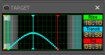
As soon as the RA and DEC fields are populated, the Target widget lights up with information about M42's rise, transit and setting times today:
Read more about this in the Target Widget section.
- Click the Goto button
 and the OK button in the popup asking us to confirm the action, and our simulated mount will slew to M42's coordinates.
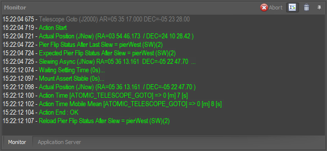
 - Watch the Monitor window at the bottom of the Voyager window for a scrolling log of the actions Voyager is taking:
Whenever Voyager is executing an action or DragScript, useful information about the current run will show up in the Monitor window and the Status window. The information is also saved to a Log file in the Log folder.
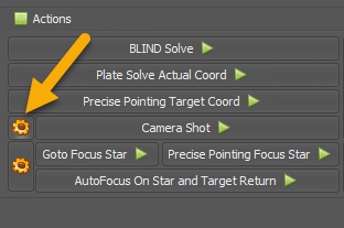
Now that we have pointed the scope at M42, we can take a quick simulated picture.
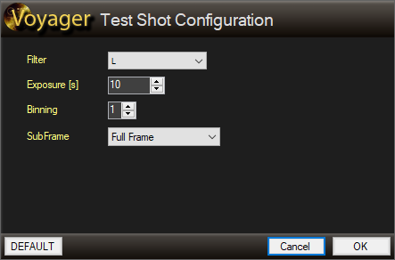
This will bring up the Test Shot dialog window:
You can use any settings you like, but these are fine. This will take a 10 second simulated exposure with binning level 1x1, full frame, and using the L filter.
- Click the OK button accept your settings and close the window
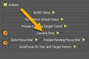
- Now click the Camera Shot button to take the exposure:
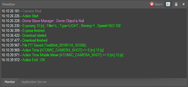
Watch the Monitor window to see the progress of the Camera Shot action:
Congratulations, you've taken your first (simulated) exposure with Voyager! Now let's define a Sequence, which lets us take a bunch of images with a single command.
Define a Sequence
A Sequence is the Voyager's main way to take a series of images of a single target. Depending on the target's availability in your night sky, a single sequence could run for many hours.
You can run multiple sequences with a DragScript, Voyager's drag and drop scripting language. A DragScript can automate an entire night's imaging, from startup to shutdown including taking flats and calibration frames.
For now, we will define a single sequence and use it to take five images each of M42 through four filters, L, R, G and B.
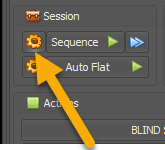
- Click the gear icon next to the Sequence button to bring up the Sequence Configuration dialog window
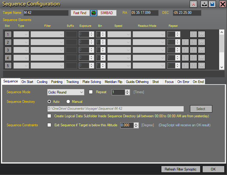
The Sequence Configuration window will have the target name and coordinates filled out already since we entered them in the Target Coordinates panel earlier in this tutorial
- Click the gray box with a 1 in it in the Slot column:
It will turn green and the fields in that row are activated
- Select Light in the Type drop-down list
- Select L in the Filter drop-down list
- Type an L in the Suffix field - this will include the filter label, L, in the saved image filename. You can put any static text in this field to include it in the filename. Filenames will automatically include the target name, image type, exposure length, binning level, camera temperature, a timestamp, and a sequence number
- Enter 10 in the Exposure field. You can enter any length (in seconds) in this box. We choose ten seconds to make the tutorial run go faster, but if you are using your actual equipment and taking real images, use whatever exposure length works for your gear
- Leave the Bin field at 1. This will take the exposure with binning level 1x1.
- Enter 5 in the Repeat field. This tells Voyager to take five exposures of M42 with the L filter
Your filled out Slot 1 should look like this:
Now repeat this process for the R, G and B filters.
Note: As of Voyager 2.1.1f, there are Copy and Paste buttons for each Sequence Element line. For this example, you can click Copy on the R (second) line and then Paste on the third and fourth lines to copy the element values. Then change the Filter and Suffix on the third line to G, and on the fourth line to B.
Your finished Sequence Elements panel should look like this:
Below the Sequence Elements you will see a bar like this:
It shows the order in which images will be shot with your choice of color filters. In this case, it tells us we will cycle through the L, R, G and B filters five times, as the default sequence mode is "Cyclic Round."
- Click OK to save your settings and close the Sequence Configuration window. There are many more configuration options available for a sequence, but especially since we are running with simulators, let's just run this and see what happens.
Run the Sequence
- Click the Sequence button with the green triangle to run the sequence.
- Unless you have changed your setup options to start a sequence without confirmation, you will get a pop up window asking if you really want to run the sequence. Click OK
The sequence should start running immediately. You can watch its progress in the Monitor window. Messages will scroll by telling you what Voyager is currently doing, along with interesting status information.
Messages in the Monitor window are color coded, as explained in the Monitor Window section.
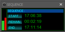
Additionally, the Sequence widget in the Status window displays information about the currently running sequence
The green bar tells you what fraction of the sequence has completed. The red bar shows the same thing for the current exposure. The time values tell you when the sequence began, how much time is left, and what the estimated time of completion will be.
Congratulations, you:
- Defined an equipment profile
- Selected a target and searched for its coordinates
- Slewed to the target
- Took a test exosure
- Defined a sequence and ran it to capture 20 images using four different filters
Next Steps
We used a very basic equipment profile and sequence in this tutorial.
Try creating a basic equipment profile using your actual equipment. Clone this profile or use the Profile Save As... menu to save a new profile so you don't write over your simulator profile.
Then try repeating the steps of selecting a target, slewing to it, taking an exposure, and running a sequence. If your mount's goto is not accurate, you may move it to the desired target with your hand controller or setup up Plate Solving and use Precise Pointing to get your target right in the middle of your field of view.
Click through the tabs of the Sequence Configuration window to try more of the options available for a sequence. For more information on what these options do, read the Sequence Configuration section.

