Difference between revisions of "Research Survey"
| (6 intermediate revisions by the same user not shown) | |||
| Line 49: | Line 49: | ||
Most of the settings are the same as the Sequence Configuration window so this will be familiar if you have set up sequences before. | Most of the settings are the same as the Sequence Configuration window so this will be familiar if you have set up sequences before. | ||
| − | As of Voyager 2.0.14e (daily build) or 2.1.0 (stable build), you can edit sequences associated with any profile, not just the one currently loaded and active in Voyager. The "Change Profile To This Sequence" button in the title bar of this window brings up the dialog to do this. | + | As for Voyager 2.2.13f you can edit and import the Rotation of the Target (Sky PA or Rotator PA). As of Voyager 2.0.14e (daily build) or 2.1.0 (stable build), you can edit sequences associated with any profile, not just the one currently loaded and active in Voyager. The "Change Profile To This Sequence" button in the title bar of this window brings up the dialog to do this. |
| Line 119: | Line 119: | ||
<br /> | <br /> | ||
| − | {{Note|Gain and Offset are only available when using the Voyager ASI Camera native driver. They are not available if you use the ASCOM driver}} | + | {{Note|Gain and Offset are only available when using the Voyager ASI or QHY Camera native driver. They are not available if you use the ASCOM driver}} |
==Target Tab== | ==Target Tab== | ||
| Line 127: | Line 127: | ||
*'''RA J2000''': Enter the RA of your target | *'''RA J2000''': Enter the RA of your target | ||
*'''DEC J2000''': Enter the DEC of your target | *'''DEC J2000''': Enter the DEC of your target | ||
| + | *'''Rotation °''': Enter the Rotation angle used by Voyager to positioning the rotator. Can be Sky PA or Rotator PA, depends on how you configure it in the Rotator configuration tab | ||
*'''Order''': Enter a number representing the order in which your target should be run. If no value is entered here, targets run in the order listed | *'''Order''': Enter a number representing the order in which your target should be run. If no value is entered here, targets run in the order listed | ||
*'''RoboClip:''' opening the RoboClip for import a single target from the database (not a mosaic with Virtual FOV) | *'''RoboClip:''' opening the RoboClip for import a single target from the database (not a mosaic with Virtual FOV) | ||
| Line 137: | Line 138: | ||
**IC10;00 20 24.33;+59 18 06.7;1 | **IC10;00 20 24.33;+59 18 06.7;1 | ||
**IC166;06 27 05.37;+59 05 03.5;2 | **IC166;06 27 05.37;+59 05 03.5;2 | ||
| − | **Here's a sample file with the correct import format: [ | + | **Here's a sample file with the correct import format: [http://www.starkeeper.it/voyager/log.csv log.csv] <br /> |
*'''Verify''' '''Data''': Click this button after editing the list to apply your settings - this does not validate the data, it merely makes your changes active | *'''Verify''' '''Data''': Click this button after editing the list to apply your settings - this does not validate the data, it merely makes your changes active | ||
*'''Refresh Filter Synoptic''': Refreshes the filter synoptic display - the color bar under the Sequence Elements table that represents the amount of time and order of shots taken by filter color | *'''Refresh Filter Synoptic''': Refreshes the filter synoptic display - the color bar under the Sequence Elements table that represents the amount of time and order of shots taken by filter color | ||
| Line 169: | Line 170: | ||
**'''Auto / Manual''': Choose Auto and Voyager will automatically create a sequence directory using the base folder specified in [https://voyager.tourstar.net/Voyager_Setup#PATH Voyager Setup] and the Target Name. Choose Manual and you can type in any folder for your images, or click the Select button and browse to a directory to choose that one | **'''Auto / Manual''': Choose Auto and Voyager will automatically create a sequence directory using the base folder specified in [https://voyager.tourstar.net/Voyager_Setup#PATH Voyager Setup] and the Target Name. Choose Manual and you can type in any folder for your images, or click the Select button and browse to a directory to choose that one | ||
**'''Create Logical Data Subfolder Inside Sequence Directory (all between 00:00 to 08:00 AM are from yesterday)''': Check this box to create a subfolder, named with the date of the start of the sequence. All images from this sequence are stored in the subfolder, including any taken after midnight until 8AM local time | **'''Create Logical Data Subfolder Inside Sequence Directory (all between 00:00 to 08:00 AM are from yesterday)''': Check this box to create a subfolder, named with the date of the start of the sequence. All images from this sequence are stored in the subfolder, including any taken after midnight until 8AM local time | ||
| + | |||
| + | * '''Sequence Sub Foldering / File Naming:''' selection of the sub foldering and file naming method | ||
| + | ** '''Use FILE PATTERN:''' flag this checkbox to activate sub foldering and file naming with File Pattern method (please configure the file pattern in the File Pattern Manager) | ||
| + | ** '''Use Voyager STANDARD:''' flag this checkbox (this choice is the default for a new sequence) to use the original sub foldering and file naming system adopted by Voyager from the beginning | ||
| + | *** '''Create Logical Data Subfolder Insside Sequence Directory (all between 00:00 to 08:00 AM are from yesterday) :''' create a subfolder under the target folder with a YYYY-MM-DD format , file within 00:00 to 08:00 wil be put in a folder from the previous day date | ||
| + | *** '''Create Data Subfolder for Filter Name:''' create a sub folder with the target name | ||
<br /> | <br /> | ||
| Line 214: | Line 221: | ||
*'''On Driver Goto Error''': If the mount driver returns an error when Voyager commands a Goto (slew) operation, retry the operation up to a maximum of 3 times | *'''On Driver Goto Error''': If the mount driver returns an error when Voyager commands a Goto (slew) operation, retry the operation up to a maximum of 3 times | ||
*'''Meridian Flip Watchdog:''' if checkd abort the sequence of running target if Voyager try for the times indicated to do a Meridian Flip but mount report wrong side of Pier or side of pier calculated is wrong | *'''Meridian Flip Watchdog:''' if checkd abort the sequence of running target if Voyager try for the times indicated to do a Meridian Flip but mount report wrong side of Pier or side of pier calculated is wrong | ||
| + | |||
| + | |||
| + | ==Rotator Tab== | ||
| + | The Rotator tab of the Sequence Configuration window is where you specify additional parameters for your rotator's actions during the sequence: | ||
| + | |||
| + | [[File:RotatorTab2213c.jpg|link=https://wiki.starkeeper.it/index.php/File:RotatorTab2213c.jpg]] | ||
| + | *'''Rotator Manage:''' if check rotator's action will be managed during the sequence framing the target with the PA specified and other all the others flag available | ||
| + | *'''Rotator Type:''' define if the rotation angle is the rotator angle (rotator PA) reported from the driver (and with offset if asked to Voyager in Sync) or the Sky angle (Sky PA) chosen with web dashboard VirtualFOV or planetarium or another system. If you select Sky PA Voyager will use the Plate solve PA result to rotate the rotator to the right angle. If you select the Rotator PA Voyager will just rotating rotator using drive angle at desidered value, no correction using the plate solved PA will be done | ||
| + | *'''PA Tollerance +/-:''' specified the tollerance in degree about the PA accepted like ok (example 180° +/-3° will accept 177° to 183°) | ||
| + | *'''Rotator & Meridian Flip:''' "Mantain the Same Image Orientation After the Meridian" if checked force Voyager to shot the target with same orientation in the images taken before anf after meridian. In this case if you have chosen Rotator PA like Rotation type the rotator will be flipped if the mount is after the meridian, if you chosen Sky PA the PA will retained also after the meridian triggering a rotator flip.Use this flag is useful also to use always the same guide star in case of use of OAG or system with high focal lenght. | ||
| + | *'''Rotator & Fork Mount:''' if enabled force Voyager to check rotator tolleranze after each Target realign, useful for fork mount with derotator system | ||
| + | {{Note|Rotator management will be done only done in this two points of the sequence: | ||
| + | |||
| + | - at first precise pointing, so flag the “Point target on start” in the start tab of the sequence configurator | ||
| + | |||
| + | - at meridian change | ||
| + | }} | ||
Revision as of 21:01, 27 April 2021
Research & Survey Mosaic Section
The Research & Survey Mosaic section lets you take a series of images of one or more targets at different times mantaining a complex constraints in a really simple way. For example, :
- Exoplanets .. you may be looking for exoplanets, and want to image the same stars with known exoplanets several times a night
- Asteroids and Comets .. you may also use the research and survey to look for moving objects, such as asteroids or comets
- Supernovae Galaxies Survey .. or perhaps you want to take images of a number of galaxies every night, looking for supernovae.
- Messier Marathons .. you may want to catch all the visible in the night Messier objects.
- Mosaic .. you can also shot incredible Mosaic of Deep Sky using togheter with the Voyager VirtualFOV facilities based on Web Dashboard
You can enter the Research & Survey Mosaic section two different ways:

- From the Command Bar at the top of the Voyager window, click the icon pointed at by the red arrow

- From the Section menu, click the Research menu item on the ribbon
Research & Survey Mosaic Workspace
Once you enter the Research & Survey Mosaic workspace, if you have some targets defined for your research survey mosaic, your workspace will look something like this:

- Action Info: This panel displays information about the Research & Survey Mosaic sequence that has been configured by clicking the gear
 icon.
icon. - The values shown in the first lines of this window depend on how you have configured the sequence. We will explain what the fields mean by using the field values from this screen shot:
- Project: The type of Survey ... for now this is a fixed value
- TestUnguided: The value of the Research Name field in the Research & Survey Mosaic configuration
- C:\Users\leonardo\Documents\Voyager\ConfigSequence\TestUnguided.e2q: If a Research & Survey Mosaic sequence file has been loaded, this is its pathname and filename. This will default to the values you specified when you installed Voyager, but it can be anywhere that you manually chose when you saved the file
- Sequence Target Table: This table shows the targets and progress if the sequence is running (as in this example) or has completed.
- BLUE/GREEN ARROW ICON: up pointing if object is rising before meridian, down if passed meridian and going to set
- TARGET NAME: Name from the data table in the Research & Survey Mosaic sequence configuration
- RA J2000: RA coordinates of the target from the data table in the Research & Survey Mosaic sequence configuration
- DEC J2000: DEC coordinates of the target from the data table in the Research & Survey Mosaic sequence configuration
- PA°: Position Angle of the Target to use to manage the rotator position (Sky PA or Rotator PA depends on setting in the Rotator configuration Tab
- ALT: Altitude of the target at the time the sequence exposures were started
- TIME START: Starting time when the exposures of this object were taken
- TIME END: Time when the exposures of this object finished
- TIME: Elapsed time to complete the exposures
- STATUS: Blank if nothing has run, DONE if this step is complete, RUNNING if it is currently running, SKIPPED_ALTITUDE if step bypassed for low altitude, DONE_ERROR is completed with an error
Research & Survey Mosaic Configuration
Most of the settings are the same as the Sequence Configuration window so this will be familiar if you have set up sequences before.
As for Voyager 2.2.13f you can edit and import the Rotation of the Target (Sky PA or Rotator PA). As of Voyager 2.0.14e (daily build) or 2.1.0 (stable build), you can edit sequences associated with any profile, not just the one currently loaded and active in Voyager. The "Change Profile To This Sequence" button in the title bar of this window brings up the dialog to do this.

- Project: Any name you would like to use to identify your configuration
- Profile: The equipment profile associated with this sequence. A new sequence will default to using the currently active profile. You can create and edit sequences for non-active profiles by clicking the Change Profile to This Sequence button in the title bar of this window
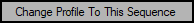 Change Profile to This Sequence: Brings up a dialog window from which you can change the profile assigned to this sequence. See Change Sequence Profile section for discussion of the migration process
 Reset Sequence Data: Caution! Clicking this button resets all information in the sequence. If you have not saved it, your sequence data will be lost and you will have to start over
 Open Sequence File: Click this file to load the data from a saved sequence into the Research & Survey Mosaic Configuration window
 Save Sequence File: Click this file to save the data from the Research & Survey Mosaic Configuration window to the file of your choice
 Cancel and Close Window: Click this button to close the Research & Survey Mosaic Configuration window and discard any changes made since it was opened
- Refresh Filter Synoptic: Refreshes the filter synoptic display - the color bar under the Sequence Elements table that represents the amount of time and order of shots taken by filter color
- OK: Click the OK button to save your changes and close the Research & Survey Mosaic Configuration window
Change Sequence Profile
As of Voyager 2.0.14e (daily build) or 2.1.0 (stable build), you can create and edit sequences with the profile of your choice.
If you only edit or create sequences for the active profile, there is no need to use this dialog window. The active profile is used, and the filename of the active profile will be stored with the sequence when you save it.
By default, a new sequence will be created using the currently active profile, which is displayed on the right at the top of the Voyager main window.
References to the "Actual" profile mean the currently active profile in Voyager.
If you want to create or edit a sequence using a different profile from the currently active one, click the Change Profile to This Sequence button in the Sequence Configuration title bar to bring up this dialog:

- Data:
- Sequence: The sequence file currently being worked on. If you have created a new sequence and it has not yet been saved, this field will be blank
- Original Profile: The profile stored with the sequence file
- Actual Profile: The profile currently loaded and active in Voyager
- APPLY Actual Profile: Ignore the profile stored in the sequence file and use the currently active profile in Voyager. If settings such as filters are different between the two profiles, carefully review your sequence elements and make sure you are using the desired filters, speed and readout mode
- USE Original Profile: Use the profile stored in the sequence file for things like filters, camera gain and readout. This is useful if you want to edit a sequence for a different profile than the currently active one.
- SELECT MANUALLY Profile: Opens a file browsing dialog and you can select any profile. The selected profile will be used to supply information such as filters, camera readout and gain settings when editing this sequence, and the selected profile will be stored in the sequence file when you save it
- CANCEL: Abort the sequence profile changes and close this window without saving changes
Sequence Elements
The Sequence Elements panel of the Research & Survey Mosaic configuration window is where you define the exposures to take for each target:

- Slot: Click the gray buttons in the Slot column and they turn green indicating that slot is active - the information in that row (slot) of the Sequence Elements table will be used when you run the sequence
- Type: Exposure type: Light, Bias or Dark
- Filter: Filter for this exposure. Available filters come from the connected profile in the Camera Setup area
- Suffix: Enter any suffix you would like to include in the image filename. The name of your filter is a good choice.
- Exposure: Length of the exposure in seconds
- Bin: Binning level for this exposure. Available binning levels come from the connected profile in the Camera Setup area
- Speed: ISO for DSLR's
- Readout Mode: Select a Readout Mode from the drop-down list. Readout Modes are retrieved from your camera if your camera driver provides them. The Readout Mode section of the Camera Setup page explains how to retrieve them
- Gain: If you are using the ASI Camera native driver supplied by Voyager (not the ASI ASCOM driver), you can enter the Gain for this sequence element. This will be grayed out if you are not using Voyager's ASI Camera native driver.
- Offset: If you are using the ASI Camera native driver supplied by Voyager (not the ASI ASCOM driver), you can enter the Offset for this sequence element. This will be grayed out if you are not using Voyager's ASI Camera native driver.
- Important Note! If you are using a sequence with the ASI Camera native driver that was first defined with a different camera, all Gain and Offset values will be initially set to 0/0. Make sure you change these to the desired settings and save the sequence before running.
 : Click the magnifying glass icon to select the Gain and Offset from the presets defined in the ASI Camera native driver setup.
- Repeat: Number of exposures to take
 :
:
- Up arrow moves this row up one position; Down arrow moves this row down one position; X clears the information from this row
- Copy Button: Click Copy to copy the sequence element information from the row containing the Copy button
- Paste Button: After clicking Copy on a row, click Paste on a new row to paste the sequence element information to the row containing the Paste button
- Use copy and paste to quickly set up the sequence elements for a number of rows that only differ in a couple of values, such as the filter choice
- The scroll bars on the right can be used to scroll the window up and down if you have more rows than show in the main window
- The color bar under the Sequence Elements is the "Filter Synoptic." This is a visual representation of the amount of time spent imaging each filter, in the order that the filters will be used. In this example, the red, green and blue filters are used in sequence, with an equal amount of time spent shooting each filter (60 seconds). The color bars have an equal size for each color, representing 60 seconds of red, 60 seconds of green, and 60 seconds of blue.
Target Tab
The Target Tab of the Research & Survey Mosaic configuration window contains two sub-tabs. The first one is a data table listing the names, coordinates, and order in which to run your targets:
- Name: Enter the name of your target
- RA J2000: Enter the RA of your target
- DEC J2000: Enter the DEC of your target
- Rotation °: Enter the Rotation angle used by Voyager to positioning the rotator. Can be Sky PA or Rotator PA, depends on how you configure it in the Rotator configuration tab
- Order: Enter a number representing the order in which your target should be run. If no value is entered here, targets run in the order listed
- RoboClip: opening the RoboClip for import a single target from the database (not a mosaic with Virtual FOV)
- Remove: remove the target from the Data
- Disabled: if check the Research & Survey Mosaic Sequence will not be runned for this target, trget will be skypped and to reported i nthe dashboard area
- Clear All: Click this button to clear the target data table
- Import Mosaic Panels from RoboClip Virtual FOV: import your targets as panels of mosaic from RoboClip just in one click, the target in RoboClip must be a Mosaic realized with the Virtual FOV facilities of Voyager
- Import Targets from CSV file: Import your targets from a CSV file with four columns formatted like this. The first line with column names is mandatory. You can have as many lines as you want in your CSV file.
- TARGET;RA;DEC;ORDER
- IC10;00 20 24.33;+59 18 06.7;1
- IC166;06 27 05.37;+59 05 03.5;2
- Here's a sample file with the correct import format: log.csv
- Verify Data: Click this button after editing the list to apply your settings - this does not validate the data, it merely makes your changes active
- Refresh Filter Synoptic: Refreshes the filter synoptic display - the color bar under the Sequence Elements table that represents the amount of time and order of shots taken by filter color
The second sub-tab of the Target tab is Running Options:

- Min Altitude: The minimum altitude in degrees at which exposures will be taken of the target. When the target is below this altitude, it will be skipped in the sequence
- Force Starting from This Target: Choose a target from the drop-down list to start the sequence with exposures of it
- Repeat Loop Mode: Choose a loop mode from the drop-down list
- Just One Time: Run the sequence once for each target in the data table
- Repeat for X times: Run the sequence X times, where X is the value entered in the "Repeat for X times" counter field on the right
- Infinite Loop: Run the sequence continuously until either all targets are below the "Min Altitude" value, or the time interval specified in the On End tab has elapsed - or the absolute end time has been reached
- Invert Order Each Target Repeat: If checked, when running the sequence more than once on the targets in the data table, reverse the order in which they are run for each loop. E.g., if the targets are T1, T2, T3, run them in that order on the first loop, and then T3, T2, T1 on the second, etc.
- Not Allow Meridian Recrossing During a Loop: If checked, if the meridian is crossed during a loop, skip any targets on the opposite side of the meridian during this loop. When the loop executes the next time, the meridian will be crossed and those targets will run.
- Abort Action if One Element of Loop was done with error: If checked, if an error occurs on a single target in a loop, the loop will be finished and then the sequence will abort
- Time Wait After First Pointing to Target: If checked, wait the number of seconds specified after initially pointing to a target. This allows the mount to settle after moving and before exposures begin
Sequence Tab
The Sequence tab of the Research & Survey Mosaic window is where you specify how the slots should be ordered and where images should be stored:

- Sequence Mode: Choose Cyclic Round or Group By Slot from the drop-down list
- Cyclic Round: Voyager will take one exposure using the parameters of a slot, then move to the next slot and take one exposure, etc. E.g. if you have one slot for each filter of L, R, G and B, Voyager would take one L exposure, then one R, then G, then B, then cycle back around to L and repeat until the total number of exposures specified in the Repeat box are taken.
- Group By Slot: Voyager will take the number of exposures specified in the Repeat column for each slot before moving on to the next slot.
- Sequence Directory: Where to save images taken during this sequence
- Auto / Manual: Choose Auto and Voyager will automatically create a sequence directory using the base folder specified in Voyager Setup and the Target Name. Choose Manual and you can type in any folder for your images, or click the Select button and browse to a directory to choose that one
- Create Logical Data Subfolder Inside Sequence Directory (all between 00:00 to 08:00 AM are from yesterday): Check this box to create a subfolder, named with the date of the start of the sequence. All images from this sequence are stored in the subfolder, including any taken after midnight until 8AM local time
- Sequence Sub Foldering / File Naming: selection of the sub foldering and file naming method
- Use FILE PATTERN: flag this checkbox to activate sub foldering and file naming with File Pattern method (please configure the file pattern in the File Pattern Manager)
- Use Voyager STANDARD: flag this checkbox (this choice is the default for a new sequence) to use the original sub foldering and file naming system adopted by Voyager from the beginning
- Create Logical Data Subfolder Insside Sequence Directory (all between 00:00 to 08:00 AM are from yesterday) : create a subfolder under the target folder with a YYYY-MM-DD format , file within 00:00 to 08:00 wil be put in a folder from the previous day date
- Create Data Subfolder for Filter Name: create a sub folder with the target name
On Start Tab
The On Start tab of the Research & Survey Mosaic configuration window is where you can specify things to do before starting the sequence:

- Run this Program/Script BEFORE Time Wait: Click the box with "..." to bring up the Run External Program / Script window to browse to a program or script to run before the "Time Wait on Start" interval
- Time Wait On Start: Specify if Voyager should delay before starting the sequence
- Interval: Check this box and enter the amount of time to wait in HH:MM:SS in the three scrolling fields. Voyager will wait this amount of time before starting the sequence
- Absolute: Check this box and enter the actual time in HH:MM:SS at which Voyager should start running the sequence
- Run this Program/Script AFTER Time Wait: Click the box with "..." to bring up the Run External Program / Script window to browse to a program or script to run after the "Time Wait on Start" interval
- Point Target On Start: Check to perform a precision pointing operation at sequence start
- Inject Focus on Start: Check to perform an autofocus operation at first target of sequence at start
- Inject Focus on Start of Each Target: Check to perform an autofocus operation at start of each target sequence
- Open Flat Device Cover: Check to open the flat device at sequence start
- On Start: Open the flat device cover as soon as the sequence is executed - do not wait if there is a "Time Wait On Start" specified
- After Time Wait on Start: Open the flat device cover after the Time Wait On Start interval has elapsed
Cooling Tab
The Cooling tab of the Research & Survey Mosaic configuration window is where you specify CCD cooling (Peltier) for the sequence:

- Cooling: Check this box to manage cooling via this Sequence. If you don't check this box and have cooling set before running the sequence, no changes to cooling will be made.
- SetPoint: Enter the desired sensor temperature (SetPoint) for your CCD cooler
- Use CCD Firmware Cooldown: If checked, just command the desired temperature to the CCD cooler and let the cooler's firmware decide how quickly to ramp to that temperature
- Power ON After Time Wait On Start: If checked, send a command to turn CCD cooler power on after the Time Wait On Start interval has elapsed
- Auto Scale SetPoint if CCD can't cooling at initial desired request: If checked, if the CCD cooler fails to reach the desired temperature within the time specified in Camera Setup, or within the power usage constraints listed below, try again with successively warmer temperatures as specified below
- Or if Cooler Power Mobile Mean is >=: Begin the auto scaling operation if the moving average of the cooler power in use was greater than or equal to the specified percentage for the "in the last" number of seconds
- And use in order this SetPoint in °C: Use these temperatures in the order specified for auto scaling. The temperatures should be progressively warmer (higher numbers) from left to right
Pointing Tab
The Pointing tab of the Research & Survey Mosaic configuration window is where you specify additional parameters for any Pointing operations performed during the sequence:

- On Driver Goto Error: If the mount driver returns an error when Voyager commands a Goto (slew) operation, retry the operation up to a maximum of 3 times
- Meridian Flip Watchdog: if checkd abort the sequence of running target if Voyager try for the times indicated to do a Meridian Flip but mount report wrong side of Pier or side of pier calculated is wrong
Rotator Tab
The Rotator tab of the Sequence Configuration window is where you specify additional parameters for your rotator's actions during the sequence:

- Rotator Manage: if check rotator's action will be managed during the sequence framing the target with the PA specified and other all the others flag available
- Rotator Type: define if the rotation angle is the rotator angle (rotator PA) reported from the driver (and with offset if asked to Voyager in Sync) or the Sky angle (Sky PA) chosen with web dashboard VirtualFOV or planetarium or another system. If you select Sky PA Voyager will use the Plate solve PA result to rotate the rotator to the right angle. If you select the Rotator PA Voyager will just rotating rotator using drive angle at desidered value, no correction using the plate solved PA will be done
- PA Tollerance +/-: specified the tollerance in degree about the PA accepted like ok (example 180° +/-3° will accept 177° to 183°)
- Rotator & Meridian Flip: "Mantain the Same Image Orientation After the Meridian" if checked force Voyager to shot the target with same orientation in the images taken before anf after meridian. In this case if you have chosen Rotator PA like Rotation type the rotator will be flipped if the mount is after the meridian, if you chosen Sky PA the PA will retained also after the meridian triggering a rotator flip.Use this flag is useful also to use always the same guide star in case of use of OAG or system with high focal lenght.
- Rotator & Fork Mount: if enabled force Voyager to check rotator tolleranze after each Target realign, useful for fork mount with derotator system
- at first precise pointing, so flag the “Point target on start” in the start tab of the sequence configurator
- at meridian change
Tracking Tab
The Tracking tab of the Research & Survey Mosaic Configuration window is where you specify additional parameters for your mount's tracking actions during the sequence:
![]()
- Tracking Stop Watchdog: If checked, if tracking stops during the sequence, attempt to restart tracking the specified number of times
- Tracking Start: If checked, stop tracking when the sequence is started, and start tracking only after the Time Wait On Start interval has elapsed
Plate Solving Tab
The Plate Solving tab of the Research & Survey Mosaic Configuration window is where you specify additional parameters for plate solving during the sequence:

- Disable Plate Solving: If checked, do not perform plate solving during the sequence. If this is checked, precision pointing can not be done, only unverified goto's of the mount
- Bypass General Setting and use Actual Filter for Plate Solving: If checked, the filter in use for image exposures will be used for plate solving, regardless of the settings specified in Plate Solve setup
Meridian Flip Tab
The Meridian Flip tab of the Research & Survey Mosaic Configuration window is where you specify additional parameters for meridian flip management during the sequence:

- Meridian Flip Mode: Choose Do Not Manage, Halt on Flip Time or Manage from the drop-down list
- Do Not Manage: Voyager will not perform any meridian flip management during the sequence - it will not monitor mount position near the meridian while the mount is tracking
- Halt on Flip Time: When Voyager determines it is time to flip the mount, the sequence will be halted. If you have tracking safety stop enabled in Voyager the mount will be halted. Otherwise, set a limit in your mount configuration settings to stop tracking
- Manage: Voyager will monitor the mount position relative to the meridian and perform a meridian flip as needed, as specified in Mount Setup
- Flip Rotator On Meridian Flip: If checked, if a rotator is attached, flip the rotator 180 degrees after a meridian flip so the image's position angle is maintained
- Inject Focus On Meridian Flip: If checked, perform an autofocus after the meridian flip completes
- Force Meridian Flip Procedure with Exposure Abort After Meridian Crossing: If checked, Voyager will abort any exposure in progress and force a meridian flip after the Wait Max Time number of minutes has elapsed past the meridian
- ABORT Exposure if Meridian Flip occour outside Voyager and FORCE EXECUTE Meridian Flip operations: if checked Voyager try to recognize a change of pier outside Voyager and start the operation needed and/or asked in Voyager for the meridian flip. The flag work only if the mount control in Voyager is an ASCOM Driver, ASCOM Pier mode in Voyager is setting like ASCOM Normal or ASCOM Inverted and Meridian Flip Mode (Above) is setting like MANAGED
Guide/Dithering Tab
The Guide/Dithering tab of the Research & Survey Mosaic Configuration window is where you specify additional parameters for guiding and dithering management during the sequence. The settings in Guiding Setup are used unless these settings override them.

- Guide Star Selection Method: Choose how the guide star should be selected
- Voyager RoboGuide: Voyager's own RoboGuide algorithm, as specified in Guiding Setup, will be used to select a guide star. If RoboGuide cannot find a suitable guide star, Voyager will retry with the guiding software's own guide star selection process if it has one
- Native Guide Control: Use the guiding software's own star selection method
- Calibrate Guide: If checked, use this exposure in seconds and binning level for the guide software's calibration routine
- Guiding: If checked, use this exposure in seconds and binning level for the guide software's guiding exposures. Enter zero for the exposure time if you want to use your guide software's automatic mode, if it has one
- AO Centering: Choose None, Every Exposure or Every X Exposure from the drop-down list. This setting only works if you have an AO (Adaptive Optics) guide unit connected and your AO supports mirror homing
- None: Never perform AO Centering
- Every Exposure: Perform AO Centering after every exposure
- Every X Exposure: Specify X = number of exposures between AO Centering operations
- AO Centering: Choose None, Every Exposure or Every X Exposure from the drop-down list. This setting only works if you have an AO (Adaptive Optics) guide unit connected and your AO supports mirror homing
- Star Lost Detection: If checked, the maximum allowed percentage of time that the guide star can be lost without considering guiding to have failed
- Dithering: If checked, specify the max number of pixels to move during a dithering operation
- Realign to Target: If checked, perform a precision pointing operation after this number of minutes has elapsed. This is useful if you are doing unguided exposures and want to re-center your target every so often
Shot Tab
The Shot tab of the Research & Survey Mosaic Configuration window is where you specify additional parameters for image exposures:

- Wait Between Shot: If checked, wait the specified number of seconds after each exposure before beginning the next. May be useful for some cameras that need a pause before the next command is sent to take an exposure
- On Exposure Error: If checked, if an exposure results in an error, try to re-take the exposure up to 3 times
- Use SubFrame: If checked, use a centered subframe of the size selected from the drop-down list: Full Frame, 1/2 size, 1/4 size, 1/8 size, 1/16 size or CUSTOM size.
- CUSTOM Size: If you choose custom size from the drop-down, a counter appears from which you can choose any percentage value for your subframe size
Focus Tab
The Focus tab of the Research & Survey Mosaic Configuration window is where you specify additional parameters for autofocus operations.
The settings in AutoFocus setup are used unless these settings override them.

- Focus Method: Choose the autofocus method to use during the sequence
- Voyager RoboStar: Use Voyager's RoboStar method to select the star for Voyager's single-star VCurve autofocus operation
- Voyager LocalField: Use Voyager's LocalField multiple-star autofocus operation
- Focus Star: Use the focus star specified by the Focus Star panel below and use Voyager's VCurve single-star autofocus operation
- FocusMax AcquireStar: Use FocusMax for autofocus and request that it use its own AcquireStar method to select a star for autofocus
- Focus On Place: Autofocus using a suitable star, if one can be found, in the current field of view
- Use Low Precision Pointing: If checked, relax the error tolerance for precision pointing to the focus star.
- Multiple Max Allowed Error by: If Use Low Precision Pointing is checked, multiply the error tolerance specified in Mount Setup by the number of times specified in the counter. E.g., if you specified an error tolerance of 10 arc-secs in Mount Setup, and a "5" here, the focus star precision pointing operation would stop when the error was less than 50 arc-secs.
- Max HFD Variation Percentage Allowed: Maximum amount of variation of the focus star's HFD (Half Flux Diameter) allowed. Larger values are considered an autofocus failure
- Force RoboStar on First Focus: If checked, use the RoboStar operation on first autofocus to find a suitable focus star and perform a VCurve autofocus operation
- On LocalField Focus Error use RoboStar: If checked, if a LocalField autofocus operation fails, try RoboStar to find a suitable focus star and perform a VCurve autofocus operation
- Focus Star Setting: Specify a star to use for autofocus before the meridian, after the meridian, or at all times.
- If only the left column - Before Meridian - is filled out, that star is used for the entire sequence.
- If both columns are filled out, the coordinates on the left are used before the meridian and the star on the right is used after the meridian
 : Click this icon to bring up the Object Finder and search for your focus star by name. The Object Finder will populate the RA, DEC and NAME fields from the search result
- Focus Filter:
- Use Actual Filter: Autofocus using the filter for the currently running slot of the sequence
- Use Default Filter: Choose the default filter to use for autofocus operations. If nothing else overrides this selection, use the filter selected from the drop-down list.
- Focus Trigger: Check one or more boxes to determine the condition(s) that trigger an autofocus
- Focus By Slot: If checked, and if the sequence mode is Group By Slot, autofocus at the start of every new sequence slot.
- Focus Each X Exposure: If checked, focus every X exposures, where X is the counter value.
- Focus Each X Minutes: If checked, focus every X minutes, where X is the counter value. This can be especially useful if your sequence mixes slots with very different exposure lengths.
- Focus Each X Delta °C or Delta ADU: If checked, focus every X degrees °C change of temperature or change of ADU value reported by the focuser chosen in Setup. Check your focuser documentation to see whether it reports temperature or a value of ADU that is related to temperature. Then choose the counter value based on how much the number returned by the focuser changes when you need to rerun autofocus.
- Focus Each X Delta Degrees of Altitude: If checked, focus every time the target's altitude changes by the specified number of degrees
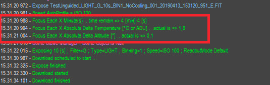
- As of Voyager 2.1.1f, new Monitor Window information lines have been added at the start of each exposure explaining the autofocus criteria currently in effect along with current status of each criterion:

On End Tab
The On End tab of the Research & Survey Mosaic Configuration window is where you specify actions Voyager should take at the end of a sequence:

- Force Sequence End Timer: If checked, end the sequence after the time Interval specified has elapsed (HH:MM:SS)
- Absolute: If checked, end the sequence at the absolute time indicated in the counter fields (HH:MM:SS)
- Finish Running Exposure: If checked, finish any exposure in progress when the Force Sequence End Timer is triggered
- Do this at END:
- Nothing: If this radio button is selected, do nothing at the end of the sequence
- Warmup: If this radio button is selected, warmup the CCD cooler at the end of the sequence
- Sync Warmup: If checked, wait for the warmup to finish. If not checked, send the warmup command to the cooler and don't wait
- Good Night: if this radio button is checked, Voyager will perform the following shutdown actions at the end of the sequence:
- Run this Program/Script BEFORE: Click the "..." button to choose an external program or script to run at the start of the Good Night operation. Click the X button to clear this field
- Move CCD to Filter: If checked, move the filter wheel to the filter selected from the drop-down list
- Async Warmup: If checked, send a command to the CCD cooler to warm the sensor, and do not wait for the warmup operation to complete
- Sync Warmup: If checked, send a command to the CCD cooler to warm the sensor, and wait for the warmup operation to complete
- Park: If checked, park the mount
- Run this Program/Script AFTER: Click the "..." button to choose an external program or script to run at the end of the Good Night operation. Click the X button to clear this field