Flat Device Setup
Color Coding
Throughout the Setup workspace, Voyager uses color to indicate the following:
- Black: A normal setting
- Gold or Yellow: Use caution when changing as things may not work well or as expected
- Red: Use extreme care when changing this setting - the wrong value can damage your equipment or the imaging session may fail
Flat Device Setup Workspace
Voyager 2.1.0a and later supports one or two Flat devices. Flat devices are illuminated panels that either fit on the end of your telescope or are mounted on a wall, and provide even illumination for the taking of "Flat frames," used to calibrate your astro images.
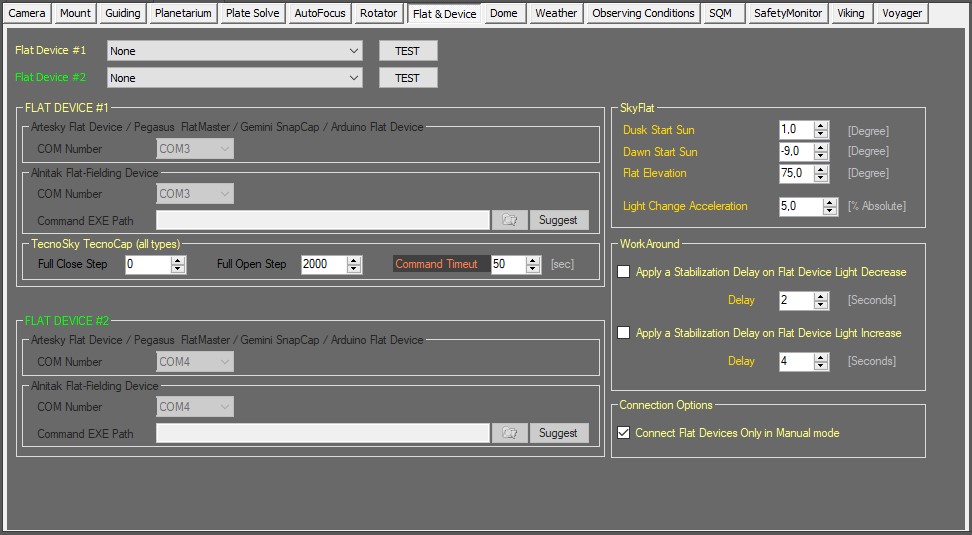
Click the Flat Device button in the Setup workspace to display the Flat Device setup window:
Flat Device #1 Choice
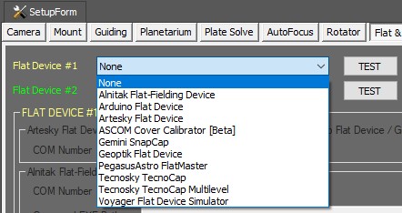
Choose your flat device from the drop-down list at the top of the Flat Device setup window. Use Flat Device #1 to setup a Tecnosky flat devices. All other flat devices are supported by both Flat Device #1 and #2.
- Flat Device: Choices include None, Gemini SnapCap, Alnitak Flat-Fielding Device (Flip-Flat), Voyager Flat Device Simulator, Tecnosky TecnoCap, Arduino Flat Device, Tecnosky TecnoCap Multilevel and Artesky Flat Device, PegasusAstro FlatMaster, Geoptik Flat Device
- TEST: Click the TEST button and Voyager will test the connection to the flat device. Only the connection is tested, no other functions of the flat device
Flat Device #2 Choice
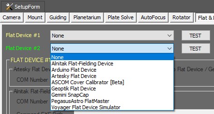
Choose your flat device for flat device #2 from the drop-down list.
- Flat Device: Choices include None, Gemini SnapCap, Alnitak Flat-Fielding Device (Flip-Flat), Voyager Flat Device Simulator, Arduino Flat Device, Artesky Flat Device, PegasusAstro FlatMaster
- TEST: Click the TEST button and Voyager will test the connection to the flat device. Only the connection is tested, no other functions of the flat device
Artesky Flat Device / Geoptik Flat Device / Pegasus FlatMaster / Gemini SnapCap / Arduino Flat Device COM Port
The Artesky Flat Device / Geoptik Flat Device / Pegasus FlatMaster / Gemini SnapCap / Arduino Flat Device panel of the Flat Device Setup workspace is where you specify the COM port used by your device:
- COM Number: Choose the COM port number from the drop-down list for your Gemini SnapCap or Arduino flat device.
The Arduino flat device is this one or a compatible device: https://github.com/jwellman80/ArduinoLightbox
Alnitak Flat-Fielding Device
The Alnitak Flat-Fielding Device panel of the Flat Device Setup workspace is where you specify the COM port and location of the EXE file that controls your Alnitak flat device:
- COM Number: Choose the COM port number from the drop-down list for your Alnitak flat device.
- Command EXE Path: Click the folder icon to browse to the location of the AACmd.exe file. This is the executable program that controls your Alnitak flat device. You must install the software that came with your Alnitak flat device before you can use it from Voyager
- Suggest: Click this button and Voyager will fill out the Command EXE Path field with the default path used in the installation of the Alnitak flat device control software
TecnoSky TecnoCap (all types)
The TecnoSky TecnoCap panel of the Flat Device Setup workspace is where you specify configuration parameters for TecnoSky flat devices:
- Full Close Step: The position in steps of the TecnoSky device when it is fully closed
- Full Open Step: The position in steps of the TecnoSky device when it is fully open
- Command Timeout: Maximum time in seconds to wait after issuing a command for the command to complete before considering the operation to have failed
ASCOM Cover Calibrator Device
If you are using an ASCOM Cover Calibrator Device n the Flat Device #1 and/or Flat Device #2 panel:
- Calibrator Actions Timeout: expressed in milliseconds (1000ms is equal to 1s) set the max time a Voyager actions using the calibrator (light source) will wait for the action to finish, after this time the action will be aborted to avoid hangup.
- Cover Actions Timeout: expressed in seconds set the max time a Voyager actions using the cover (cap) will wait for the action to finish, after this time the action will be aborted to avoid hangup.
Sky Flat
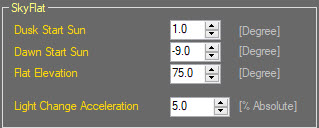
Starting with Voyager 2.1.1a, sky flats are supported. The default parameters should work well, but you can modify them here:
- Dusk Start Sun: The solar elevation at which dusk is considered to begin
- Dawn Start Sun: The solar elevation at which dawn is considered to begin
- Flat Elevation: The altitude to point the telescope when taking sky flats
- Light Change Acceleration: The acceleration of changing light conditions for setups with very low focal ratio or unfavorable latitudes
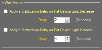
Workaround
Some workaround to apply during to Auto Flat device tasks. Depends on Flat devices used.
- Apply a Stabilization Delay on Flat Device Light Decrease: if Voyager decrease light of flat device panel, during auto flat, will apply a delay before continue with next steps. This to allow electronics to stabilize light brightness.
- Delay: delay after decrease in terms of seconds
- Apply a Stabilization Delay on Flat Device Light Increase: if Voyager increase light of flat device panel, during auto flat, will apply a delay before continue with next steps. This to allow electronics to stabilize light brightness.
- Delay: delay after increase in terms of seconds
Connection Options
Some options to use for Flat devices connection during setup connection in Voyager.
- Connect Flat Devices Only in Manual Mode: if checked Flat Devices can be connected to Voyager only in manual mode from startup commands. This is useful if you want to connect the flat device just at finish or begin of your imaging session without disconnect and reconnect all the setup devices.
Spike-A-Flat
All-Pro Software sells the Spike-A-Flat series of flat panels. http://www.spike-a.com/flatfielders/
To use this from Voyager, install the ASCOM driver available from All-Pro here: https://adgsoftware.com/alnitak_emu/
The sample Javascript file included with the ASCOM driver download shows the Javascript needed to connect to the Spike-A-Flat's ASCOM driver and set the brightness from 0 to 1023.
Determine the brightness levels needed to create flats with your equipment, and use that brightness level in the SetSwitchValue command. You may need a different value for narrow band and RGB filters.
Here's an example of JavaScript to set the brightness to 75:
var X = new ActiveXObject("ASCOM.SpikeAFlatFielder.Switch");
X.Connected = true;
X.SetSwitchValue(0, 75);
X.Connected = false;
Use a text editor such as Notepad to save this code in a file ending with .js, such as SpikeAFlatLevel75.js.
Use a brightness value of 0 to turn the panel off.
var X = new ActiveXObject("ASCOM.SpikeAFlatFielder.Switch");
X.Connected = true;
X.SetSwitchValue(0, 0);
X.Connected = false;
You can then call these .js files to set the panel brightness before taking your flat frames. You can call them using a DragScript action or from an Auto Flat sequence.
Other Flat Panel Devices
If you use a flat panel that is not natively supported by Voyager but has an interface you can call from a script file, create script files to turn it on, set the brightness and turn it off. Call those script files using a DragScript action or from an Auto Flat sequence when taking your flat frames.
