AutoFocus Setup
AutoFocus Setup Video
There is a video on setting up AutoFocus on the Voyager Astro Imaging YouTube Channel
AutoFocus Setup Workspace
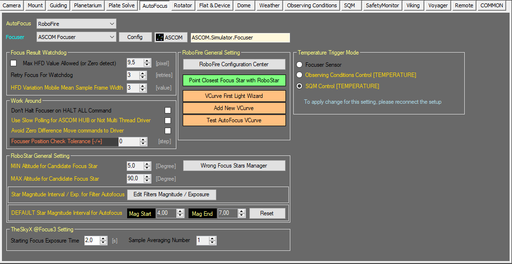
The AutoFocus Setup workspace is where you store settings for Voyager's autofocus operations:
Color Coding
Throughout the Setup workspace, Voyager uses color to indicate the following:
- Black: A normal setting
- Gold or Yellow: Use caution when changing as things may not work well or as expected
- Red: Use extreme care when changing this setting - the wrong value can damage your equipment or the imaging session may fail
Avoid different Thickness Filter Set
Using filter with different thickness is something to avoid. This cause focus shift between set of filters and can cause autofocus failure.
If unfortunately you are in this situation you can mitigate this in Voyager by:
- create and use a dedicated profile for narrow band filter without broadband filters
- in the sequence override the plate solve fitler with one narrow filter and increase binning and exposure time for solving (https://wiki.starkeeper.it/index.php/Sequence_Configuration#Plate_Solving_Tab)
- change the Near Focus setting of RoboFire increasing for how much is needed to recognize the HFD value when you switch to narrow filter and for sure not using LocalField autofocus (https://wiki.starkeeper.it/index.php/AutoFocus_Setup#VCurve_Mode_Tab). At start of focus an HFD lower than Near Focus parameter will abort the focus process.
AutoFocus Choice
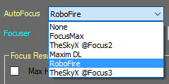
Select the AutoFocus program you want to use at the top of the AutoFocus Setup workspace:
- AutoFocus: Select the autofocus program from the options in the drop-down list
- Available selections include None, FocusMax, TheSkyX @Focus2, Maxim DL, RoboFire, and TheSkyX @Focus3
- FocusMax is a product of CCDWare: http://www.ccdware.com/products/focusmax/
- TheSkyX has two autofocus routines: @Focus2 and @Focus3. TheSkyX is a product of Software Bisque: http://www.bisque.com/sc/pages/TheSkyX-Editions.aspx
- Maxim DL is a product of Diffraction Limited: http://diffractionlimited.com/product/maxim-dl/
- RoboFire is Voyager's proprietary autofocus function, and has two options: RoboFire VCurve mode (focusing on a single star), and RoboFire LocalField (multi-star focus)
Focuser Choice
If you choose RoboFire for autofocus, you must select ASCOM Focuser from the Focuser drop-down, and then click the ASCOM button to select the focuser. Click the Config button to modify the ASCOM focuser's settings:
If you use any of the other autofocus options, you must set up the focuser in those programs, not in Voyager.
Focus Result Watchdog
The Focus Result Watchdog panel in the AutoFocus Setup workspace has several parameters controlling whether an autofocus operation is considered successful:
- Max HFD Value Allowed (or Zero detect): If checked, specify the maximum HFD (Half Flux Diameter) value in pixels beyond which the autofocus operation is considered to have failed
- Retry Focus For Watchdog: The number of times an autofocus routine will be tried before giving up
- HFD Variation Mobile Mean Sample Frame Width: The number of HFD values obtained from the autofocus action to be used for the calculation of the moving average. The value of the moving average will be used by the HFD watchdog during the Sequence at the end of each autofocus to validate the result obtained in percent.
Work Around
The Work Around panel in the AutoFocus Setup workspace contains a parameter to prevent focuser motion from stopping after a HALT ALL command:
- Don't Halt Focuser on HALT ALL Command: If checked, when a HALT ALL command is issued, which normally stops all motion, do not stop the focuser if it is moving. This is needed because sending HALT to some focuser drivers cause them to move the drawtube to the zero position.
- Use Slow Polling for ASCOM HUB or Not Multi Thread Driver: If checked, adds a delay between requests to the ASCOM focuser HUB driver. This may help for autofocus drivers that are not multi-threaded or have trouble responding quickly enough to Voyager's requests. Leave off unless needed.
- Focuser Position Check Tolerance [-/+]: If non-zero, when Voyager commands the focuser to move to a position, the move will be considered successful if the ending step value is within this many steps plus or minus from the commanded value. I.e., if a tolerance of 5 is specified, a focuser goto 1000 command will succeed if the ending position is any value between 995 and 1005. By default, this is zero and focuser commands will return an error is the ending value is different from the commanded value. It is recommended to use a value of 0 here unless your focuser has difficulty going to the commanded position, which is unusual but has been seen in some focusers. Less than optimal focus may be obtained if this value is non-zero
RoboStar General Setting
The RoboStar General Setting panel in the AutoFocus Setup workspace contains parameters for Voyager's RoboStar operation, which automatically selects a focus star:
- MIN Altitude for Candidate Focus Star: Minimum altitude allowed for the focus star when chosen by RoboStar for a VCurve AutoFocus. A star lower than this value will not be considered.
- MAX Altitude for Candidate Focus Star: Maximum altitude allowed for the focus star when chosen by RoboStar for a VCurve AutoFocus. A star higher than this value will not be considered.
- Wrong Focus Stars Manager: Click this button to bring up the RoboStar Wrong Focus Stars Black List Manager. Add stars to this list that you do not want used as focus stars. For example, a double star may not work as a focus star and could be listed here. To add a star to the list, type its name in the Name field, click the Add button, and click OK. Just add the name, and if that name exists, Voyager will add the star to the black list and also display the data for any other blacklisted stars
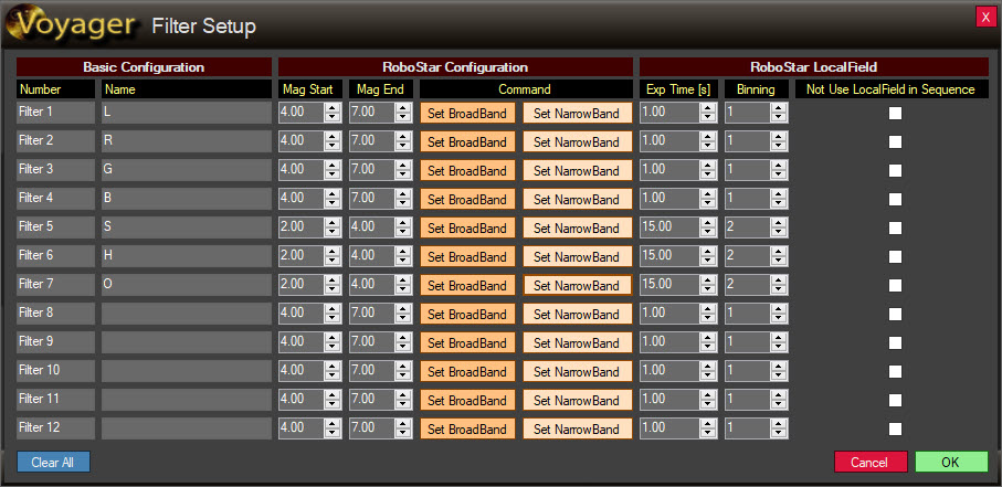
- Star Magnitude Interval / Exp for Filter Autofocus: Click the Edit Filters Magnitude / Exposure button to bring up the Filter Setup dialog where you can specify the dimmest and brightest stars to be used by the RoboStar routine when searching for a focus star. You can also specify the exposure time and binning for each filter, as well as whether or not to use each filter during a RoboFire LocalField autofocus operation during a sequence.
- Documentation for the Filter Setup dialog is here: Filter Setup
- DEFAULT Star Magnitude Interval for Autofocus: Specify the magnitude range to be used for focus stars, from the brightest (Mag Start) to the dimmest (Mag End). Click the Reset button to restore the default magnitudes.
TheSkyX @Focus3 Setting
The TheSkyX @Focus3 Setting panel in the AutoFocus Setup workspace contains parameters for TheSkyX @Focus3
- Starting Focus Exposure Time: Exposure length in seconds to be used by TheSkyX's @Focus3 autofocus routine
- Sample Averaging Number: The number of exposures to take at each focuser position by TheSkyX's @Focus3 autofocus routine
AutoFocus Temperature Trigger Mode
Contains options for selecting the temperature data source to select for generating the autofocus trigger
- Focuser Sensor: this is the default option. Data about temperature for generate the trigger for AutoFocus will be readed from focuser temperature sensor
- Observing Conditions Control [TEMPERATURE]: with this option the data about temperature for generate the trigger for AutoFocus will be readed from the observing conditions control configured in Voyager, and exactly reading the TEMPERATURE variable in the data set
- SQM Control [TEMPERATURE]: with this option the data about temperature for generate the trigger for AutoFocus will be readed from the SQM control configured in Voyager. Be sure your SQM driver are of tupe observing conditions or reports this features.
RoboFire General Setting
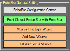
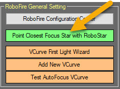
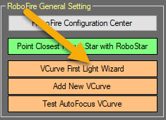
The RoboFire General Setting panel in the AutoFocus Setup workspace contains important RoboFire autofocus settings and controls, including RoboFire configuration, VCurve First Light Wizard and management, and a live action to find the closest focus star using RoboStar:
- RoboFire Configuration Center: Click this button to bring up the RoboFire Configuration Center tabbed dialog, described below in the RoboFire Configuration Center documentation
RoboFire VCurve vs. LocalField: Which to Use When?
Voyager has two different autofocus methods: VCurve (single-star) and LocalField (multiple-star).
- VCurve: VCurve autofocus is done on a single star at the center of the field of view. VCurve works best when your optics are flat - the focal point is the same across the field - or when the region of interest is in the center of the field in a portion that is flat or close to flat (same focus). For example, this is a good choice for small galaxies and planetary nebulae.
- LocalField: LocalField autofocus optimizes the average focus (HFD: Half Flux Diameter) of multiple stars across the entire field. If your optics are not flat - there is some variation across the field - and your region of interest spans the field, LocalField will give you the best focus across the entire image. For example, this is a good choice for large nebulae or star clusters taking up the entire field.
RoboFire Configuration Center
Voyager's RoboFire autofocus function is configured from the RoboFire Configuration Center panel of the AutoFocus Setup workspace. Click the RoboFire Configuration Center button to bring up the tabbed dialog box.
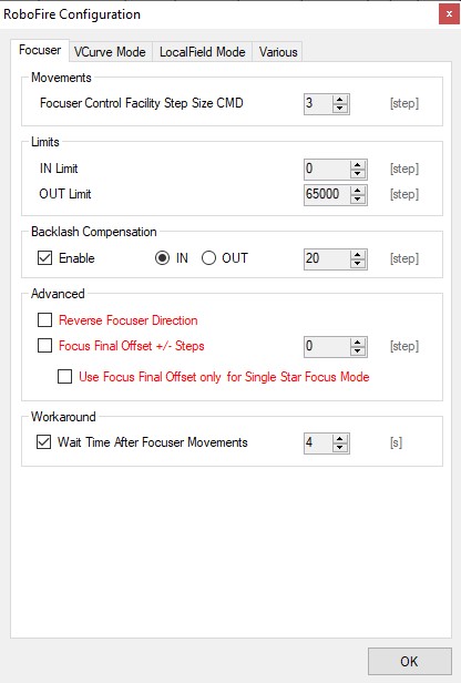
Focuser Tab
- Focuser Control Facility Step Size CMD: Number of focuser steps to move for each click of the "<" and ">" small move buttons in the RoboFire Focuser command widget . The Large Move buttons "<<IN" and ">>OUT" move this number of steps x5.
- Limits:
- IN Limit: The minimum position (furthest in) of the Focuser in steps
- OUT Limit: The maximum position (furthest out) of the Focuser in steps
- Backlash Compensation:
- Enable: Check this box to enable backlash compensation. Some focusers have "backlash," which is what happens when you reverse focuser direction and the focuser doesn't move for a number of steps because the mechanism has a bit of "play" when changing direction
- IN/OUT: If the Enable box is checked, the IN/OUT radio buttons control when backlash compensation is applied, either when moving IN or OUT. IN means backlash compensation will be done when the focuser receives a command to move IN (a compensation value will be added to the requested value in the IN direction and after the IN move is finished a move OUT will be done by the same compensation value)
- Steps: Set the number of focuser steps of backlash compensation to apply. If the Enable box is checked, RoboFire autofocus will command the focuser to move this many steps when reversing focuser direction to compensate for backlash
- Advanced:
- Reverse Focuser Direction: If checked, Voyager will treat the focuser position as reversed from normal, i.e. a smaller position number is further out, and larger numbers are further in. Please only check this setting if you are sure, as it could cause damage to your equipment if set incorrectly.
- Focus Final Offset +/- Steps: If checked, Voyager adds / subtracts this value of steps when an autofocus operation is terminated with success. This option allows you to manage optics with a zonal defect or a collimation problem that cannot be fixed
- Use Focus Final Offset only for Single Star Focus Mode: if checked and Focus Final Offset +/+ Steps option is checked the offset will be added if the current focus running is a single star type
- Workaround:
- Wait Time After Focuser Movements: if check a delay after the focuser movements will be applied. Expressed in seconds.
VCurve Mode Tab
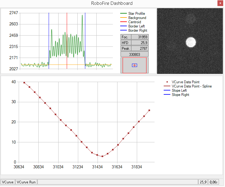
Voyager's RoboFire single star autofocus works by creating a "V Curve" representing HFD (a star's Half Flux Diameter or "size") vs. focuser position. You should run the VCurve First Light Wizard to create an initial VCurve, and the Add New VCurve operation to run additional VCurves. Running multiple VCurves can improve autofocus accuracy. The buttons you click to run these VCurve functions are in the AutoFocus Setup workspace.
VCurve from a RoboFire autofocus run
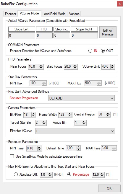
Continuing with the RoboFire Configuration dialog, the second tab is the VCurve Mode Tab, filled out with some values from running the VCurve First Light Wizard on an actual system. The values you see will look different.
- Actual VCurve Parameters (Compatible with FocusMax): If you have values from running VCurves with CCDWare's FocusMax product using the same focuser and optical system, you can manually enter them here.
- Slope Left: The slope of the left portion of the VCurve
- PID: (Position Intercept Difference): The number of focuser steps between the X-axis intercept points (where the Half Flux Diameter is zero) of the left and right VCurve lines. The smaller this value, the steeper the V Curve lines.
- Step Inc: The number of focuser steps between each measured point on the VCurve
- Slope Right: The slope of the right portion of the VCurve
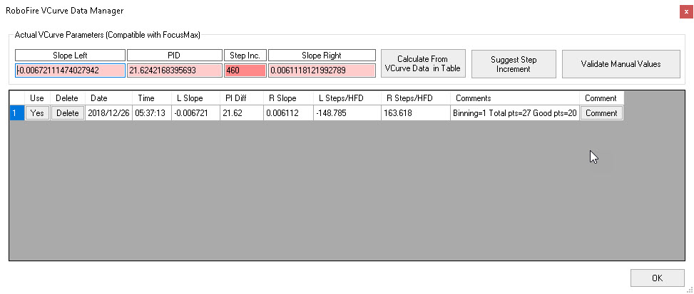
Click the Edit or Manage button in the Actual VCurve Parameters panel to bring up the RoboFire VCurve Data Manager. The Data Manager shows the current VCurve parameters being used by RoboFire autofocus and the values from runs of the VCurve First Light Wizard and any runs of the Add New VCurve function.
- Actual VCurve Parameters (Compatible with FocusMax): If you have computed a VCurve with Voyager, the VCurve parameters are shown here. If you have values from CCDWare's FocusMax using the same focuser and optical system, you can type them in here.
- Calculate from VCurve Data in Table: Click this button to calculate VCurve parameter values based on the rows in the Data Manager table below the button. Only rows with a "Yes" value in the "Use" column are included in the computation.
- Suggest Step Increment: The Step Increment is the number of focuser position steps moved between VCurve measurements. If you have data entered in the Actual VCurve Parameters table and are not sure of the proper step increment, click this button for a recommendation. Type the recommended value into the Step Inc. field to use it in RoboFire autofocus operations.
- Validate Manual Values: Click this button to verify that the values you entered in the Actual VCurve Parameters fields make sense. This doesn't guarantee proper autofocus results; it only checks the values for mathematical or logical inconsistencies.
- Use/Delete Buttons: Click the button in the Use column of the VCurve Data table to toggle between "Yes" and "No." Only rows with "Yes" in this column are used when you click "Calculate from VCurve Data in Table.
- Comment: The Comments field is populated when you run Voyager's VCurve operations. Click the Comment button in the VCurve data table row to edit the comment.
Returning to the RoboFire Configuration dialog, VCurve Mode tab:
- COMMON Parameters:
- Focuser Direction for VCurve and Autofocus: IN / OUT: Click this radio button to define the direction the focuser should move when performing a VCurve autofocus operation.
- HFD Parameters: HFD is the Half Flux Diameter of the focus star
- Near Focus: HFD value to use when running the Near Focus part of the autofocus routine. During the Near Focus routine, multiple measurements are taken of the focus star to establish its HFD, which is then used to determine where the focuser is on the VCurve. Once this position is established, the number of steps needed to reach the middle of the VCurve (in focus) can be determined.
- Start Focus: The HFD of the focus star at which to start the autofocus operation
- VCurve Limit: The HFD value at the beginning and end of the VCurve
- Star Flux Parameters:
- MIN Flux: Minimum (dimmest) flux of the focus star. The number entered is multiplied by 1000 to determine the minimum star flux
- MAX Flux: Maximum (brightest) flux of the focus star. The number entered is multiplied by 1000 to determine the maximum star flux
- First Light Advanced Settings:
- Focuser Progression: RoboFire Automata use a logaritmic search of position in power of 2 (1,2,4,8,16,32... focuser steps). If you focuser resolution is Low change the resolution of Progression from Default up to Low and Very Low Resolution. Lower is the resolution selected smaller will be the increment during the slope search in the First Light Wizard. Use it if you experience too big change in interval used by RoboFire with fast override of max HFD value in VCurve Limit Parameter. RoboFire need to find at least 3 point between the HFD Parameters selected inside the interval defined between Near Focus and VCurve Limit to allow slope calculation. Otherwise an error will be raise for few points usable for slope calculation.
- Camera Parameters:
- Bit/Pixel: BIts per pixel of the imaging camera's sensor
- Frame Width: Width in pixels of the autofocus frame - the focus star must stay in this frame during the autofocus operation. Maximum size is 1024 pixels
- Central Region: The percentage of the overall camera frame used as the central region. Focus stars must be within this region
- Target Star Bin: The binning used for the exposures taken to find the target star when RoboStar is used to find a suitable focus star
- Focus Bin: The binning used for exposures taken during autofocus
- Filter for VCurve: Filter used for exposures taken while building a VCurve
- Exposure Parameters:
- MIN Time: The shortest allowed exposure time, in seconds, for autofocus. The RoboFire autofocus routine will adjust the exposure time between the MIN and MAX to try to find a time that achieves the desired star flux parameters
- Default Time: This is the exposure time, in seconds, used for the initial image taken by the RoboFire autofocus routine
- MAX Time: The longest allowed exposure time, in seconds, for autofocus. The RoboFire autofocus routine will adjust the exposure time between the MIN and MAX to try to find a time that achieves the desired star flux parameters
- Max HFD Error for Algorithm to find Top, Start and Near Focus:
- RoboFire autofocus will take successive exposures and compare the resulting HFD's, looking for the values to converge within the specified error amount (either Absolute Diff or Percentage)
- Click one of the radio buttons - either the one before Absolute Diff or the one before Percentage - to select how the Max HFD (Half Flux Diameter) Error is determined
- Absolute Diff: If the radio button for this choice is selected, the maximum HFD error allowed is this number expressed in pixels
- Percentage: If the radio button for this choice is selected, the maximum HFD error allowed during autofocus is this percentage
LocalField Mode Tab
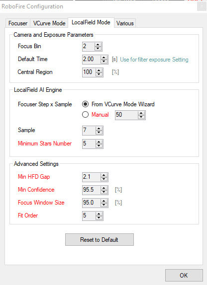
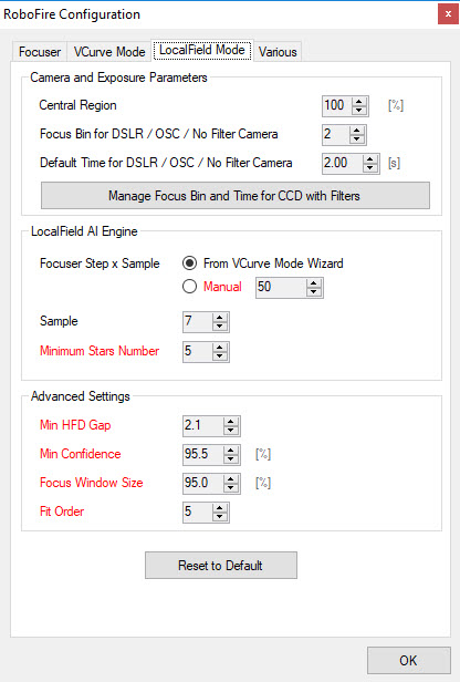
The LocalField Mode tab of the RoboFire Configuration dialog of the AutoFocus setup workspace contains parameters used by RoboFire's LocalField autofocus operation. LocalField autofocus is a multiple star focusing routine which finds the focuser position that minimizes the average HFD (Half Flux Diameter) of multiple stars in the autofocus exposures.
Prior to Voyager 2.1.1e, the LocalField tab looked like this: (see below for the new one)
- Camera and Exposure Parameters
- Focus Bin: The binning used for LocalField autofocus exposures
- Default Time: The exposure length in seconds of LocalField autofocus exposures. For the individual filter exposure times, use the Filters Setup Dialog
- Central Region: The percent of the image's central region used by the LocalField autofocus operation
- LocalField AI Engine:
- Focuser Step x Sample:
- From VCurve Mode Wizard: Choose this radio button to use the step size from the RoboFire VCurve settings. The step size is the number of steps to move the focuser between autofocus exposures
- Manual: Choose this radio button to enter the step size manually
- Sample: The number of exposures to take during the LocalField autofocus operation. One sample is taken at each focuser position
- Minimum Stars Number: LocalField autofocus will require at least this number of stars in each exposure to be successful
- Focuser Step x Sample:
- Advanced Settings:
- Min HFD Gap: a minimum pixel gap from the minimum value of HFD and maximum value of HFD found during the LocalFIeld sampling
- Min Confidence: The minimum statistical confidence percentage to consider autofocus successful
- Focus Window Size: The percentage of the image (Central Region of CCD) used during the autofocus routine
- Fit Order: Curve FIT order in AI analysis of results
- Reset to Default: Reset all LocalField Mode settings to Voyager's defaults
As of Voyager 2.1.1e, the labels in the LocalField setup tab have been changed to make them easier to understand:
- Camera and Exposure Parameters
- Central Region: The percent of the image's central region used by the LocalField autofocus operation. Reduce this percentage if you are getting out of memory errors during LocalField autofocus
- Focus Bin for DSLR/OSC/No Filter Camera: The binning used for LocalField autofocus exposures IF you are using a DSLR, One Shot Color or any camera without filters
- Default Time DSLR/OSC/No Filter Camera: The exposure length in seconds of LocalField autofocus exposures IF you are using a DSLR, One Shot Color or any camera without filters
- Manage Focus Bin and Time for CCD with Filters: If you are using a mono camera with a filter wheel, click this button to use the Filters Setup Dialog where you can specify binning and default exposure time for each filter
- LocalField AI Engine:
- Focuser Step x Sample:
- From VCurve Mode Wizard: Choose this radio button to use the step size from the RoboFire VCurve settings. The step size is the number of steps to move the focuser between autofocus exposures
- Manual: Choose this radio button to enter the step size manually
- Sample: The number of exposures to take during the LocalField autofocus operation. One sample is taken at each focuser position
- Minimum Stars Number: LocalField autofocus will require at least this number of stars in each exposure to be successful
- Focuser Step x Sample:
- Advanced Settings:
- Min HFD Gap: a minimum pixel gap from the minimum value of HFD and maximum value of HFD found during the LocalFIeld sampling
- Min Confidence: The minimum statistical confidence percentage to consider autofocus successful
- Focus Window Size: The percentage of the image (Central Region of CCD) used during the autofocus routine
- Fit Order: Curve FIT order in AI analysis of results
- Reset to Default: Reset all LocalField Mode settings to Voyager's defaults
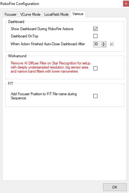
Various Tab
The final tab of the RoboFire Configuration dialog contains some miscellaneous parameters:
- Dashboard:
- Show Dashboard During RoboFire Actions: If checked, the RoboFire dashboard appears while the autofocus operations are in progress
- Dashboard on Top: If checked, keep the RoboFire Dashboard on top of other windows while it is active
- When Action Finished Auto-Close Dashboard After: If the RoboFire dashboard is displayed during the autofocus operation, this is the number of seconds to wait after autofocus completes before automatically closing the dashboard window
- Workaround
- Remove AI Diffuse Filter on Star Recognition for setup with deeply undersampled resolution, big sensor area and narrow band filters with lower nanometers: to avoid empty star recognition process for situation descripted in the label. Use only if are inside the cases written in label. THis flag is red, if you aren't sure of what to do please referring to the Voyager suppor
- FIT
- Add FOcuser Position to FIT File name during Sequence: flag this to add position of focuser (if available) to the name of FIT file will be saved
Point Closest Focus Star with RoboStar
This button starts a RoboStar operation to find a suitable nearby focus star.
VCurve First Light Wizard
Click this button to start the VCurve First Light Wizard, which walks you through all the steps needed to calculate a VCurve with your system.
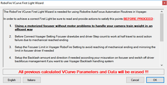
The first panel of the wizard lists important actions you must take before running the wizard. Please read and follow all these steps to avoid damage to your equipment. This information will not be repeated here - read and follow the steps in the wizard.
When you have read and followed all the steps in this panel, click the OK button to immediately run the VCurve First Light Wizard
TODO: Run the wizard and capture screen shots
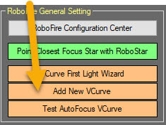
Add New VCurve
Click this button to run an immediate operation to take exposures as specified in the RoboFire Configuration Center to calculate a VCurve.
The new VCurve is stored in the VCurve data table where it can be used to refine the RoboFire autofocus VCurve. Taking several VCurves can help your autofocus results.
TODO: Run this command and capture screen shots
Test AutoFocus VCurve
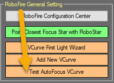
Click this button to run a RoboFire autofocus operation to test the VCurve parameters with a real life autofocus
TODO: Run and capture screen shot
