Difference between revisions of "Plate Solve Setup"
m (1 revision imported) |
|||
| (13 intermediate revisions by the same user not shown) | |||
| Line 148: | Line 148: | ||
*Search Region: Number of regions PlateSolve2 will search before giving up and returning an error for the plate solve operation | *Search Region: Number of regions PlateSolve2 will search before giving up and returning an error for the plate solve operation | ||
| − | + | ||
| + | ==PlateSolve3== | ||
| + | |||
| + | {{Note|PlateSolve 3 was written by David Rowe and is provided free of charge as a courtesy of PlaneWave Instruments, Inc}} | ||
| + | |||
| + | |||
| + | |||
| + | The PlateSolve3 panel of the Plate Solve Setup workspace contains parameters needed if you are using PlateSolve3\ for plate solving: | ||
| + | |||
| + | [[File:Immaginewefwegwg.png]] | ||
| + | |||
| + | *'''Plate Solve3 Executable Location:''' define where is the executable of PlateSolve3, use the folder seach button to specify the path and file name. Select the location where you have unzipped the installation packet of PlateSolve3 | ||
| + | *'''BLIND Mode Max Solve Time''': Maximum elapsed time in seconds allowed for PlateSolve3 to run a blind plate solve operation before considering the operation to have failed | ||
| + | |||
| + | |||
| + | {{Note|PLATESOLVE3 can be used like Plate Solving and/or Blind Solving control in Voyager.}} | ||
| + | |||
| + | |||
| + | |||
| + | Donwload the latest PlateSolve3 Package (assembled by us with original files received from [https://www.planewave.com Planewave Inc]) here: | ||
| + | |||
| + | [https://drive.google.com/file/d/1rIrOrqZ4lduU0cOXangFPsQN5fU4Mm2C/view?usp=sharing PLATE SOLVE 3 package] | ||
| + | |||
| + | Unzip and follow the instruction inside in the PlateSolve3_Instructions.txt or here written: | ||
| + | |||
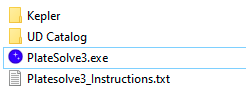
| + | # put the unzipped contents of previous downloaded zip into a new folder called PlateSolve3. The zip include UCAC4 , and GaiaDR2 catalogs , platesolve3 application and an instructions file in txt format[[File:Immagineerferfer.png]] | ||
| + | # start the platesolve3.exe application (will be opened directly in this way or go to the File menu and click on Configure Directory... ) [[File:Immagineerverv.png]] | ||
| + | # select the location for the UCAC4 as for this image (folders is located in the previous extracted one), click on browse | ||
| + | ## [[File:Immagineuikuyk.png]] | ||
| + | # again go to the File menu and click on Configure Directory... and configure the GaiaDr2 folder as for this image, click on browse button | ||
| + | ## [[File:Immagine3rf3.png]] | ||
| + | # Check that the catalogs are correctly selected , you will see the Status:OK green text under the catalogs folders as for image | ||
| + | ## [[File:Immagineefegerg.png]] | ||
| + | # close the select catalog directory form and go to menù View -> Parameters and fix the latitude and longitude fields with your location data and check the matching algoritms as for image and press ok | ||
| + | ## [[File:Immaginewerwer.png]] | ||
| + | # perform for a simple test solving one of your FIT, loading a FIT image from file menù and solving with the Tools menù -> Plate Solve | ||
| + | # close PlateSolve3, you are ready to select se it in Voyager | ||
| + | |||
| + | |||
| + | |||
==Nova.Astrometry.Net Setup== | ==Nova.Astrometry.Net Setup== | ||
The Nova.Astrometry.Net Setup panel of the Plate Solve Setup workspace contains parameters needed if you are using Astrometry.net for plate solving: | The Nova.Astrometry.Net Setup panel of the Plate Solve Setup workspace contains parameters needed if you are using Astrometry.net for plate solving: | ||
| Line 157: | Line 196: | ||
*'''BLIND Mode Max Solve Time''': Maximum elapsed time in seconds allowed for Astrometry.net to run a blind plate solve operation before considering the operation to have failed | *'''BLIND Mode Max Solve Time''': Maximum elapsed time in seconds allowed for Astrometry.net to run a blind plate solve operation before considering the operation to have failed | ||
| − | |||
| + | ==ASTAP (ASTAP3)== | ||
| + | The ASTAP Setup panel of the Plate Solve Setup workspace contains parameters needed if you are using ASTAP/ASTAP3 for plate solving/Blind solving:<br />[[File:Immagineccbm.png]] | ||
| + | |||
| + | * '''ASTAP Location''': define where is the executable of ASTAP, use the folder seach button to specify the path and file name. The default location of ASTAP (that we suggest to mantains is c:\Program Files\astap\astap.exe | ||
| + | * '''Search Radius:''' radius in degrees used for the search in plate solving mode. Suggestion is to not touch the default of 30° | ||
| + | * '''Downsample Factor:''' downscale factor of the image submitted to ASTAP engine to optimize time of search and solution. 0 means default that is 2 in ASTAP engine. Suggestion is to not touch the default of 0 | ||
| + | * '''Maximum Object:''' number of star object to identify in the ASTAP engine. Suggestion is to not touch the default of 500 | ||
| + | * '''Ignore Star Size less than:''' if you want you can define a value in arcseconds of star size to do not considering in ASTAP engine like star. Suggestion is to not touch the default not checked (not used) | ||
| + | * '''Blind Mode Max Solve Time:''' timeout in solving image in Blind Mode. Suggestion is to not touch the default of 900s | ||
| + | {{Note|We added a new ASTAP 2023 control for plate solving and blind solving. This because starting from 2022-09-08 ASTAP introduced a new rotation angle representation which forced to introduce a new check to maintain backwards compatibility. If you use a rotator and a version newest than the 2022-09-08 please use ASTAP 2023 control. All the other users can continue to use ASTAP control without any problem. | ||
| + | |||
| + | Using ASTAP control instead of ASTAP 2023 if you are using a rotator and the latest ASTAP versions can thrown an error on rotator precise positiong due to the wrong PA solved.}} | ||
| + | |||
| + | {{Note|For more info on ASTAP internal parameters and configuration we suggest to go directly to the ASTAP website or ask Support to their forum}} | ||
| + | |||
| + | == Voyager Manual Simulator == | ||
| + | The Voyager Manual Simulator isn't a real plate solve engine. Voyager when call this simulator will open a windows form where the user can edit in input the data of solving solution, this until the default timeout: | ||
| + | |||
| + | [[File:Immaginewdfwef.png]] | ||
| + | |||
| + | * '''RA J2000''': string format of RA J2000 solved (center of plate) like solution | ||
| + | * '''DEC J2000''': string format of DEC J2000 solved (center of plate) like solution | ||
| + | * '''PA''': position angle like solution | ||
| + | * '''Number of Stars''': simulate a number of stars like solution | ||
| + | * '''Focal Length''': focal lenght like solution | ||
| + | * '''Resolution ArcSec Pixel''': resolution of 1 pixel in arc seconds like solution | ||
| + | |||
| + | |||
| + | {{Note|Default data are presented reading directly from the FIT header and from profile running. RA and DEC match the RA and DEC saved in the FIT}} | ||
==Other Setup Pages== | ==Other Setup Pages== | ||
<categorytree mode="pages" depth="1">Setup</categorytree> | <categorytree mode="pages" depth="1">Setup</categorytree> | ||
Latest revision as of 18:47, 31 May 2023
Color Coding
Throughout the Setup workspace, Voyager uses color to indicate the following:
- Black: A normal setting
- Gold or Yellow: Use caution when changing as things may not work well or as expected
- Red: Use extreme care when changing this setting - the wrong value can damage your equipment or the imaging session may fail
Plate & Blind Solve Setup Workspace
The Plate Solve Setup workspace contains configuration information for the various plate solving software that Voyager can use:

Plate & Blind Solve Software Choice
The Plate Solve panel of the Plate Solve Setup workspace is where you select your choice of plate solver and blind solver:

- PLATE Solve: Select the plate solve software that Voyager should use for plate solving when the field's RA and DEC is known (at least approximately). The choices include None, PinPoint Full, TheSkyX ImageLink, PinPoint LE, All Sky Plate Solver, PlateSolve2, Nova.Astrometry.Web and ASTAP.

- BLIND Solve SW: Select the software Voyager should use for blind solving when the field's RA and DEC are unknown. The choices include None, TheSkyX ImageLink All Sky, All Sky Plate Solver, Nova.astrometry.net and ASTAP.
PinPoint is a product of DC3 Dreams: http://pinpoint.dc3.com/
PinPoint LE is a limited edition of PinPoint, bundled with MaximDL: http://www.diffractionlimited.com
All Sky Plate Solver uses the astrometry.net engine and runs it on a local Windows system under Cygwin: http://www.astrogb.com/astrogb/All_Sky_Plate_Solver.html
TheSkyX ImageLink is a component of TheSkyX from Software Bisque: http://www.bisque.com/sc/pages/TheSkyX-Editions.aspx
PlateSolve2 is a product of Planewave Instruments: http://planewave.com/downloads/software/
Nova.Astrometry.Net is an online blind solver. It is very good at solving images but your image must be uploaded so it requires an Internet connection: http://nova.astrometry.net
ASTAP is a product of Han Kleijn : http://www.hnsky.org/astap.htm
PinPoint Full Setup
The PinPoint Full Setup panel of the Plate Solve Setup workspace contains parameters needed if you use PinPoint Full version for plate solving:

- Catalog: Choose the star catalog you want to use with PinPoint from the drop-down list. The catalog must be installed and accessible from PinPoint.
- Path: Click the folder icon to browse for the path where the selected star catalog is installed
- Maximum catalog magnitude: Magnitude of the dimmest star in the selected star catalog
Here's the list of catalogs usable by PinPoint:

ASPS, PlateSolve2, PinPoint LE & Full Setup
The ASPS, PlateSolve2, PinPoint LE & Full Setup panel of the Plate Solve Setup workspace contains parameters used by all these plate solve products. Note: ASPS = All Sky Plate Solver.

- Max Solve Time: Maximum time in seconds beyond which Voyager will consider the plate solve operation to have failed
PinPoint LE, PlateSolve2
The PinPoint LE, PlateSolve2 panel of the Plate Solve Setup workspace contains parameters used by these plate solvers:

- Retry on Error: The number of times to retry the plate solve if it fails
Plate & Blind Solving Watchdog
The Plate Solving Watchdog panel of the Plate Solve Setup workspace contains information used to verify information returned by the plate solver and whether to attempt failover to blind solving:

- Check Resolution Scale Obtained vs. Profile Setting (+/-): If the checkbox is checked, then if the image resolution scale returned by the plate solver differs from the profile setting of image scale by this percentage or more, consider it an error
- Use Blind Solving if Plate Failed on Precise Pointing: Voyager uses plate solving to achieve precise pointing. If the checkbox is set, then if a precision pointing plate solve fails, try again using the blind solver.If you have blind solver we suggest to switch on this flag
Sequence Check Sync Distance
If enabled, this adds a new Sync watchdog to sequences which limit the maximum acceptable distance for which a sync can be done after plate solving.

- Enable Sync Distance Check Watchdog: If checked, the sync distance watchdog for Sequences is enabled
- Max Distance Allowed: The maximum allowed distance between the current telescope position as reported by the mount and the position returned by plate solving for a sync to be done
In this example, if the Enable Sync Distance Check Watchdog checkbox were checked:
- If the distance between the telescope position reported by the mount and the position reported by plate solving is under 300 arc minutes, a sync would be done, otherwise the sync would not be done
Plate & Blind Solving DEFAULT Setting
The Plate Solving DEFAULT Setting panel of the Plate Solve Setup workspace contains default exposure settings for plate solving:

- Exposure: Length of plate solve exposures in seconds
- Binning: Binning of plate solve exposures
- Filter: Filter to use for plate solve exposures
- Sub-Frame: Size of frame to use for plate solve exposures: Full Frame, Half Frame or Quarter Frame. For a wide field scope or big sensors, sometimes a smaller field will give better plate solving results
Precision Pointing
Voyager can either do a simple slew or Goto to a target using its RA and DEC coordinates, or perform Precision Pointing.
- Goto: Voyager sends a command to the mount to slew to the specified RA and DEC coordinates. With a simple slew or goto, Voyager does not verify that the correct target was reached and is centered in the frame; it relies on the mount's pointing model to have successfully moved to the specified coordinates
- Precision Pointing: Voyager commands the mount to slew to the specified RA and DEC coordinates, and then verifies and re-slews if necessary until the mount is pointing to the specified RA and DEC within your chosen error tolerance
- Command the mount to slew to the specified RA and DEC coordinates
- Take an exposure of the length specified in Plate Solving DEFAULT Setting
- Plate solve the image from (2); if the plate solve operation fails and the Use Blind Solving if Plate Failed on Precise Pointing setting is checked, try a Blind Solve operation
- Sync the mount if sync is allowed by the user specified setting in the Management panel of Mount Setup: Not Sync (Pointing Model Running)
- Calculate the error between the requested and actual RA and DEC coordinates
- If the error is greater than the maximum allowed specified error in Mount Setup, command the mount to move by the amount of the error and go to step (2)
If the pointing error exceeds the the maximum allowed specified error in Mount Setup, Precision Pointing is tried up to three times. If the maximum allowed error is still exceeded after three tries, the precision pointing operation will end with either an ERROR or OK status, depending on the setting of the "Use the best performance after finished pointing retries" flag in Mount Setup. If this flag is not checked, an ERROR is raised. If the flag is checked, an OK status is returned even though the mount did not achieve an error less than that specified as the maximum allowed.
Precision Pointing can be done from many places in Voyager, such as during a Sequence, in a DragScript, and from OnTheFly actions.
TheSkyX ImageLink
TheSkyX ImageLink panel of the Plate Solve Setup workspace contains parameters needed if you are using TheSkyX ImageLink for plate solving:

- Use Unknown Resolution Scale Flag: If checked, Voyager will set the "unknown resolution scale" flag when requesting TheSkyX ImageLink to perform a plate solve action. This flag may result in TheSkyX taking longer to perform a plate solve so it is better to use the image scale if you know it
All Sky Plate Solver
The All Sky Plate Solver panel of the Plate Solve Setup workspace contains parameters needed if you are using All Sky Plate Solver for plate solving:

- Near Radius Solve: ASPS will look within a radius of this many degrees to find a solution to the image when used as a plate solver
PlateSolve2
The PlateSolve2 panel of the Plate Solve Setup workspace contains parameters needed if you are using PlateSolve2 for plate solving:

- Search Region: Number of regions PlateSolve2 will search before giving up and returning an error for the plate solve operation
PlateSolve3
The PlateSolve3 panel of the Plate Solve Setup workspace contains parameters needed if you are using PlateSolve3\ for plate solving:

- Plate Solve3 Executable Location: define where is the executable of PlateSolve3, use the folder seach button to specify the path and file name. Select the location where you have unzipped the installation packet of PlateSolve3
- BLIND Mode Max Solve Time: Maximum elapsed time in seconds allowed for PlateSolve3 to run a blind plate solve operation before considering the operation to have failed
Donwload the latest PlateSolve3 Package (assembled by us with original files received from Planewave Inc) here:
Unzip and follow the instruction inside in the PlateSolve3_Instructions.txt or here written:
- put the unzipped contents of previous downloaded zip into a new folder called PlateSolve3. The zip include UCAC4 , and GaiaDR2 catalogs , platesolve3 application and an instructions file in txt format
- start the platesolve3.exe application (will be opened directly in this way or go to the File menu and click on Configure Directory... )
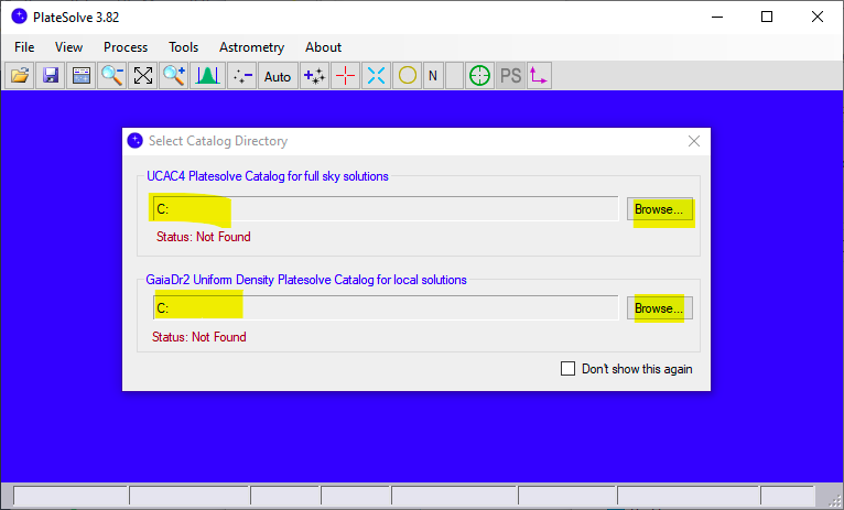
- select the location for the UCAC4 as for this image (folders is located in the previous extracted one), click on browse
- again go to the File menu and click on Configure Directory... and configure the GaiaDr2 folder as for this image, click on browse button
- Check that the catalogs are correctly selected , you will see the Status:OK green text under the catalogs folders as for image
- close the select catalog directory form and go to menù View -> Parameters and fix the latitude and longitude fields with your location data and check the matching algoritms as for image and press ok
- perform for a simple test solving one of your FIT, loading a FIT image from file menù and solving with the Tools menù -> Plate Solve
- close PlateSolve3, you are ready to select se it in Voyager


Nova.Astrometry.Net Setup
The Nova.Astrometry.Net Setup panel of the Plate Solve Setup workspace contains parameters needed if you are using Astrometry.net for plate solving:

- PLATE Mode Max Solve Time: Maximum elapsed time in seconds allowed for Astrometry.net to run a plate solve operation before considering the operation to have failed
- BLIND Mode Max Solve Time: Maximum elapsed time in seconds allowed for Astrometry.net to run a blind plate solve operation before considering the operation to have failed
ASTAP (ASTAP3)
The ASTAP Setup panel of the Plate Solve Setup workspace contains parameters needed if you are using ASTAP/ASTAP3 for plate solving/Blind solving:
- ASTAP Location: define where is the executable of ASTAP, use the folder seach button to specify the path and file name. The default location of ASTAP (that we suggest to mantains is c:\Program Files\astap\astap.exe
- Search Radius: radius in degrees used for the search in plate solving mode. Suggestion is to not touch the default of 30°
- Downsample Factor: downscale factor of the image submitted to ASTAP engine to optimize time of search and solution. 0 means default that is 2 in ASTAP engine. Suggestion is to not touch the default of 0
- Maximum Object: number of star object to identify in the ASTAP engine. Suggestion is to not touch the default of 500
- Ignore Star Size less than: if you want you can define a value in arcseconds of star size to do not considering in ASTAP engine like star. Suggestion is to not touch the default not checked (not used)
- Blind Mode Max Solve Time: timeout in solving image in Blind Mode. Suggestion is to not touch the default of 900s
Voyager Manual Simulator
The Voyager Manual Simulator isn't a real plate solve engine. Voyager when call this simulator will open a windows form where the user can edit in input the data of solving solution, this until the default timeout:

- RA J2000: string format of RA J2000 solved (center of plate) like solution
- DEC J2000: string format of DEC J2000 solved (center of plate) like solution
- PA: position angle like solution
- Number of Stars: simulate a number of stars like solution
- Focal Length: focal lenght like solution
- Resolution ArcSec Pixel: resolution of 1 pixel in arc seconds like solution